

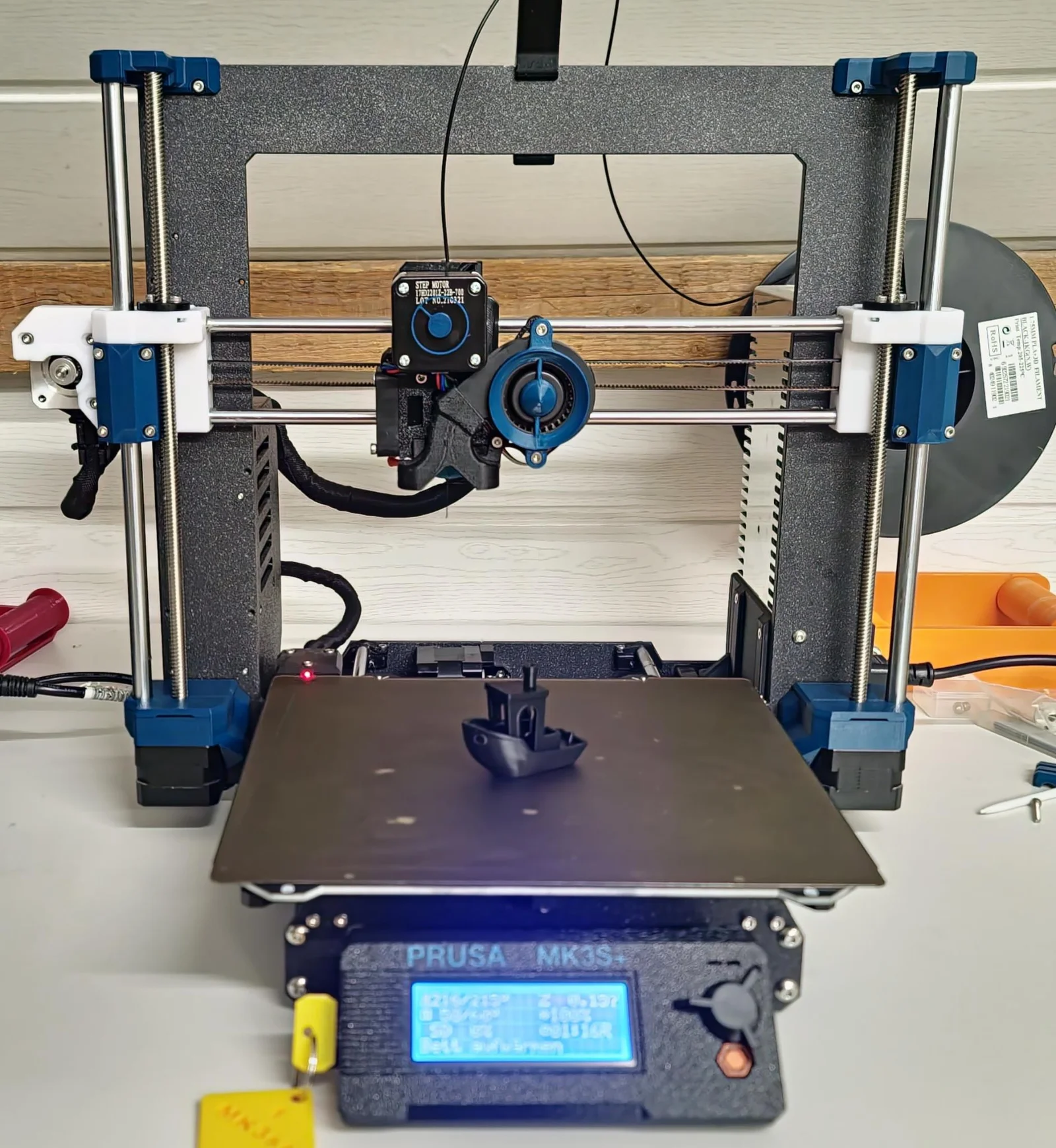
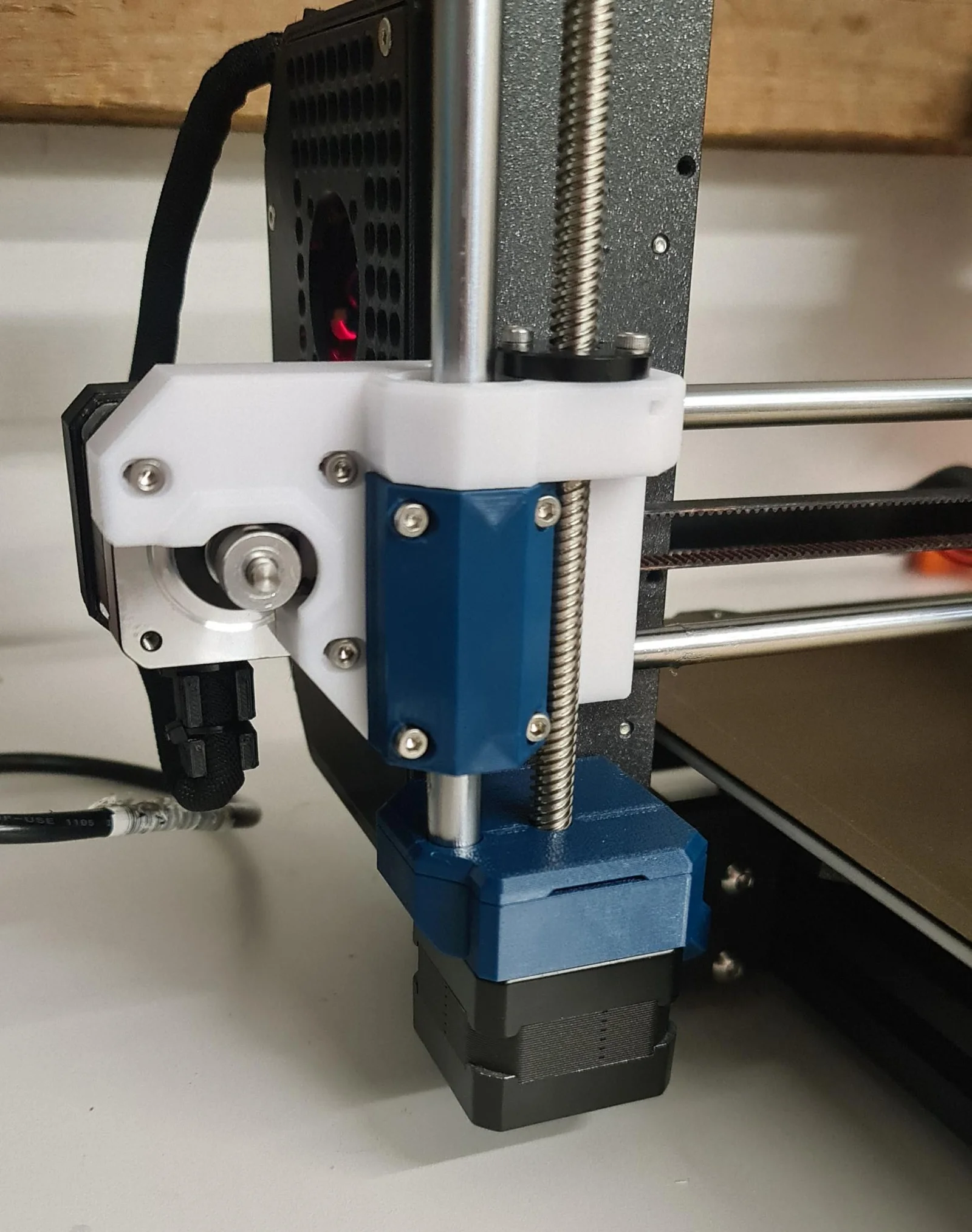


Kẹp giữ sợi Filament
 Bytinx_1344834Likes1.2KDownloads6K
Remix of Các bộ phận có thể in được cho MK4/MK3.9 By F3D Team
Build another version of this model.
The stable axes of the MK4 are designed for fast printing. The axes are only necessary on the Mk3 if you want to control the printer with Klipper and printing with high speed. Perhaps also for the MK3.5 - as the update probably does not include the Z axes of the MK4.
It doesn't make a Mk3 with standard speed any better, but it doesn't make it any worse either. Maybe the MK3 just looks a bit cooler ...
All parts of the MK3 are reused (except a few screws).
It makes no sense to reuse the 8 mm linear guides in Z of the MK3. Why, it doesn't make the MK3 any more stable - and just for the sake of looks - I think it's nonsense.
The remix is compatible with the original firmware, there are no problems with the axis calibration.
I've been working on the remix for the last 2 weeks. Changing the cad files didn't take nearly as long as installing and testing the new print parts. After each change, I installed the newly printed parts in the printer for testing, a total of 16 times ...
A big thank you to Prusa for publishing the MK4 files as a step file. It is so much easier to work with step files than fiddling with STL files.
If you have any questions or problems, please write to me.
Thank you.
https://help.prusa3d.com/guide/1b-printer-disassembly_532842#533336
Removal of the X axis, from step 11 - 15 and step 21 - 23.
https://help.prusa3d.com/guide/3-x-axis-x-carriage-assembly_529754
from step 1 to 22
In step 21, the MK3 extruder is pushed onto the linear rods instead of the three bearings.
Continue with step 30 to 34
then removing the x-carriage-back (Step 16)
https://help.prusa3d.com/guide/how-to-replace-bearings-on-the-x-axis-mk3s_214556#214720
https://help.prusa3d.com/guide/4-z-axis-assembly_529764
Mounting the Z-axis up from step 1 to step 16
and then mount the back of the extruder and the cable holder.
Please do not forget to check/adjust the height of the Pinda.
An incorrect setting can lead to errors during bed calibration.
After assembly, carry out a complete axis calibration.
The following is required for the conversion:
two linear shafts 10 x 325
two LM10LUU linear bearings (19mm x 55mm)
one longer GT2 toothed belt 6 mm x ca. 850mm
four rubber pads 20x10x1 mm (as described in the Mk4 assembly instructions)
https://help.prusa3d.com/guide/3-x-axis-x-carriage-assembly_429986#430170
a few square nuts M3nS and nuts M3n
for mounting the X-end clip
4 x M3x16 screw
4 x M3x30 screw
It would also be an advantage if you have an assortment of M3 replacement screws in stock.
Bytinx_1344834Likes1.2KDownloads6K

 Byprusa-researchLikes0Downloads2.7K

 Byarhi_585078Likes64Downloads541

 ByltloweLikes26Downloads121

 ByPengLordLikes32Downloads112

 ByHanzo3dLikes155Downloads414

 BydarienLikes0Downloads1K

 ByGeek5DLikes147Downloads485

 ByBrokentooth_designsLikes23Downloads407

 Byla-cave-au-chatLikes0Downloads965

 Bycrawler-3903250Likes0Downloads906

 ByvertigomakesLikes0Downloads562