A Spice Against Darkness

Một đèn nến nhấp nháy, dẫn đầu cho người giữ tealight với ba pin LI-ion, công tắc cảm ứng và bảng sạc.


Mô tả
Version updates:
- ‘Battery Holder’ updated to version 1.2.
- Schematic Diagram updated (charging through the BMS board).
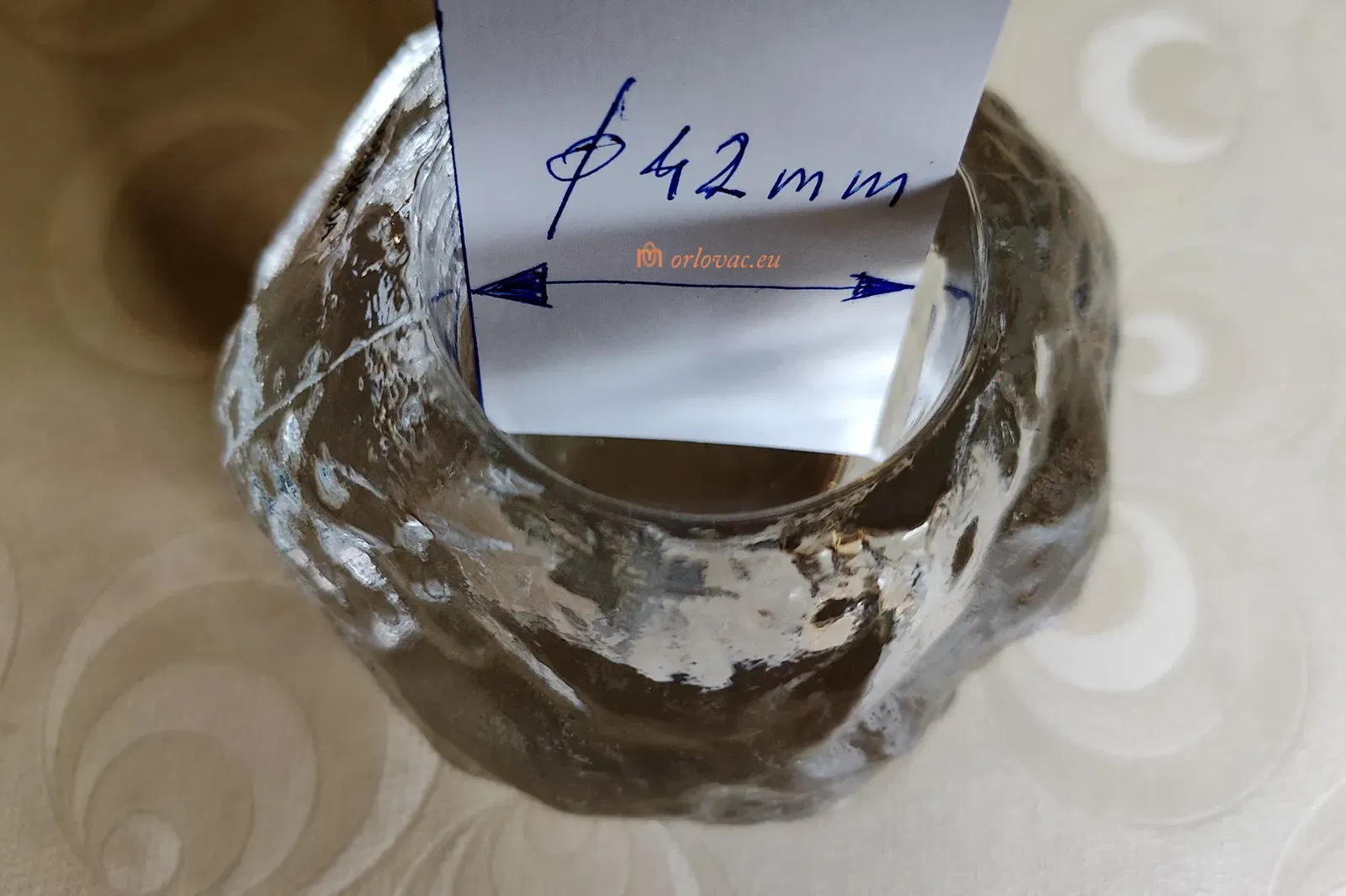
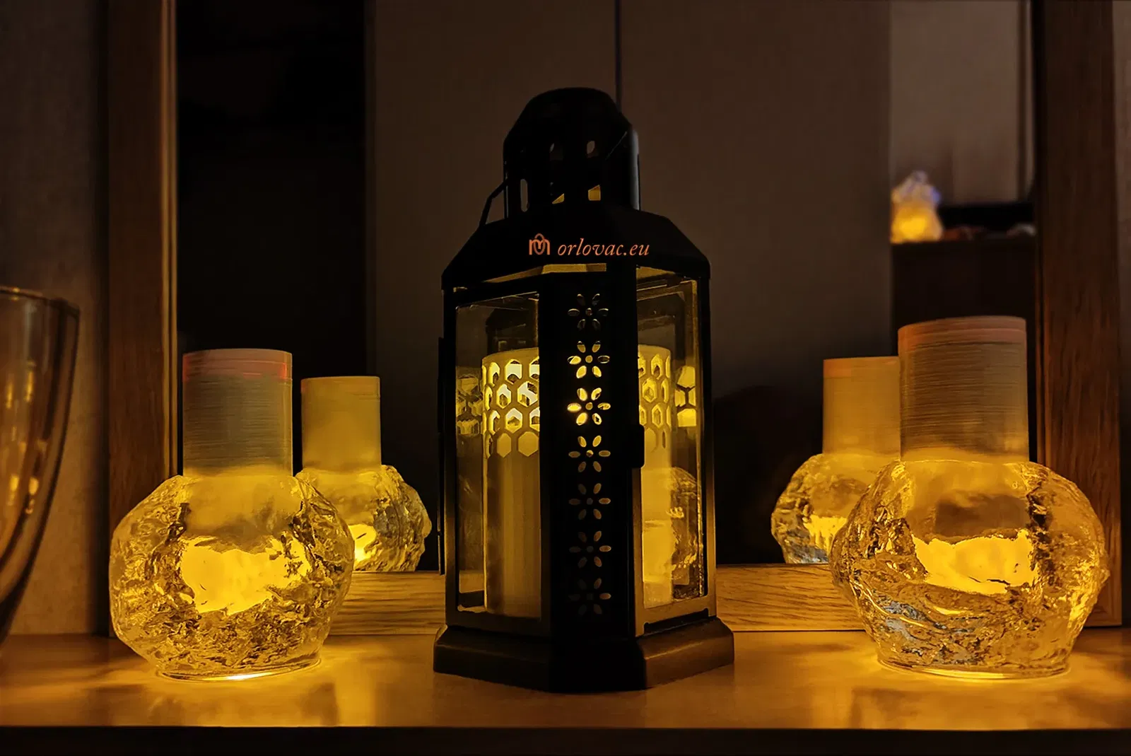
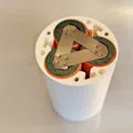
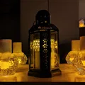
For small glass candle cups i.e. tealights. DIA 42mm (>1.6"). This is some encouragement for these dark days.
Safety first and Lithium-ion Concerns: If you do not know what your are doing or you do not have any experience about these batteries, do not play with them. They can store lot of energy, which can hurt you seriously and you can burn down your home. I have warned you and I won't be responsible for what you are doing!
Summery:
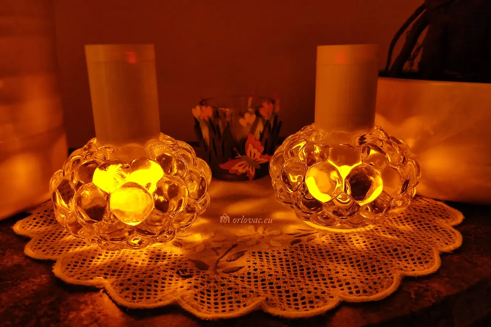
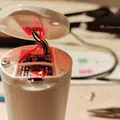
I have searched some way to lit small glass candle holders called tealights. Real candle was not an option, because of two reasons: fire hazard, and burning candle does emit lot of particles in the air, which I won't to breath in.
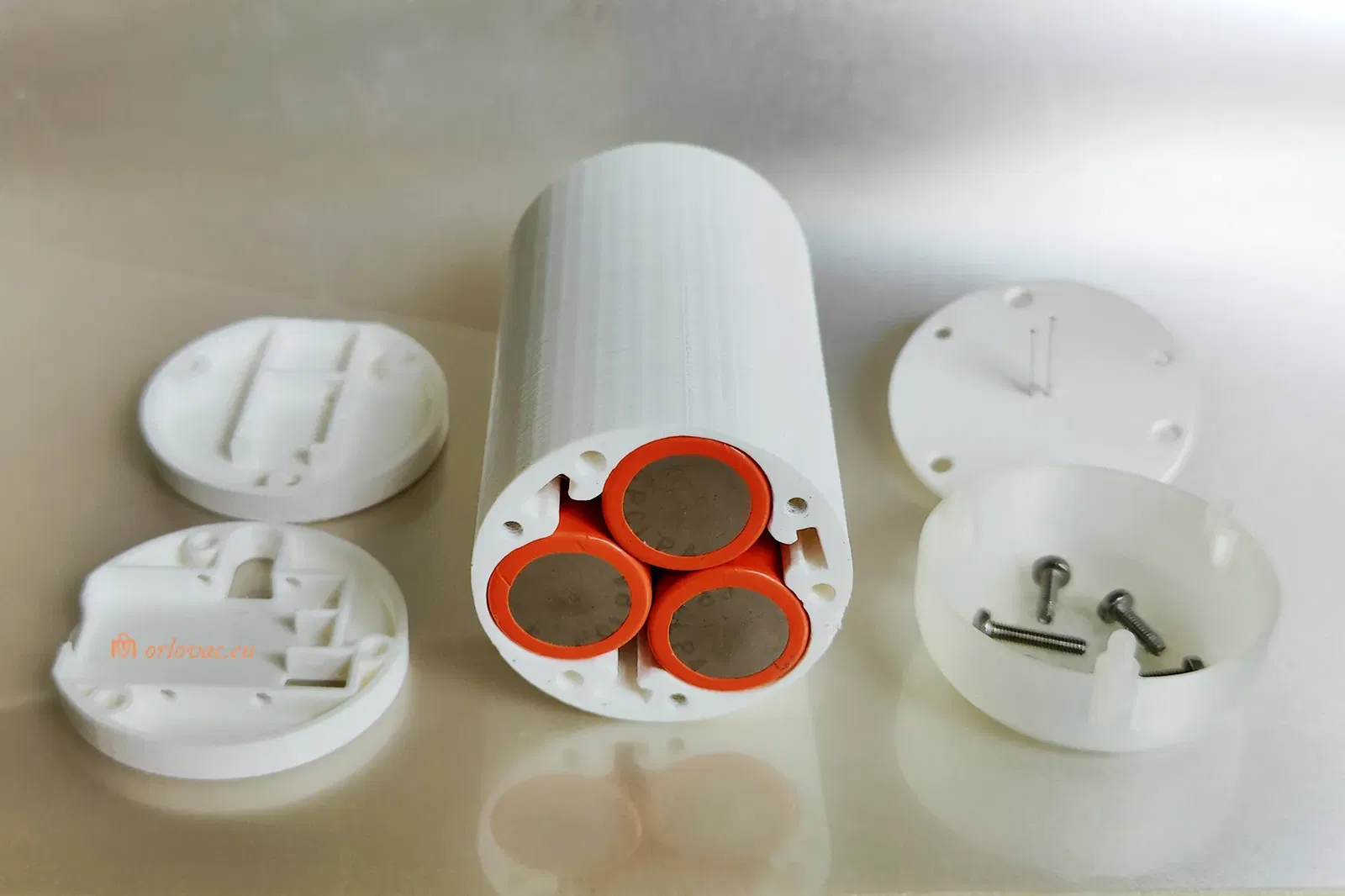
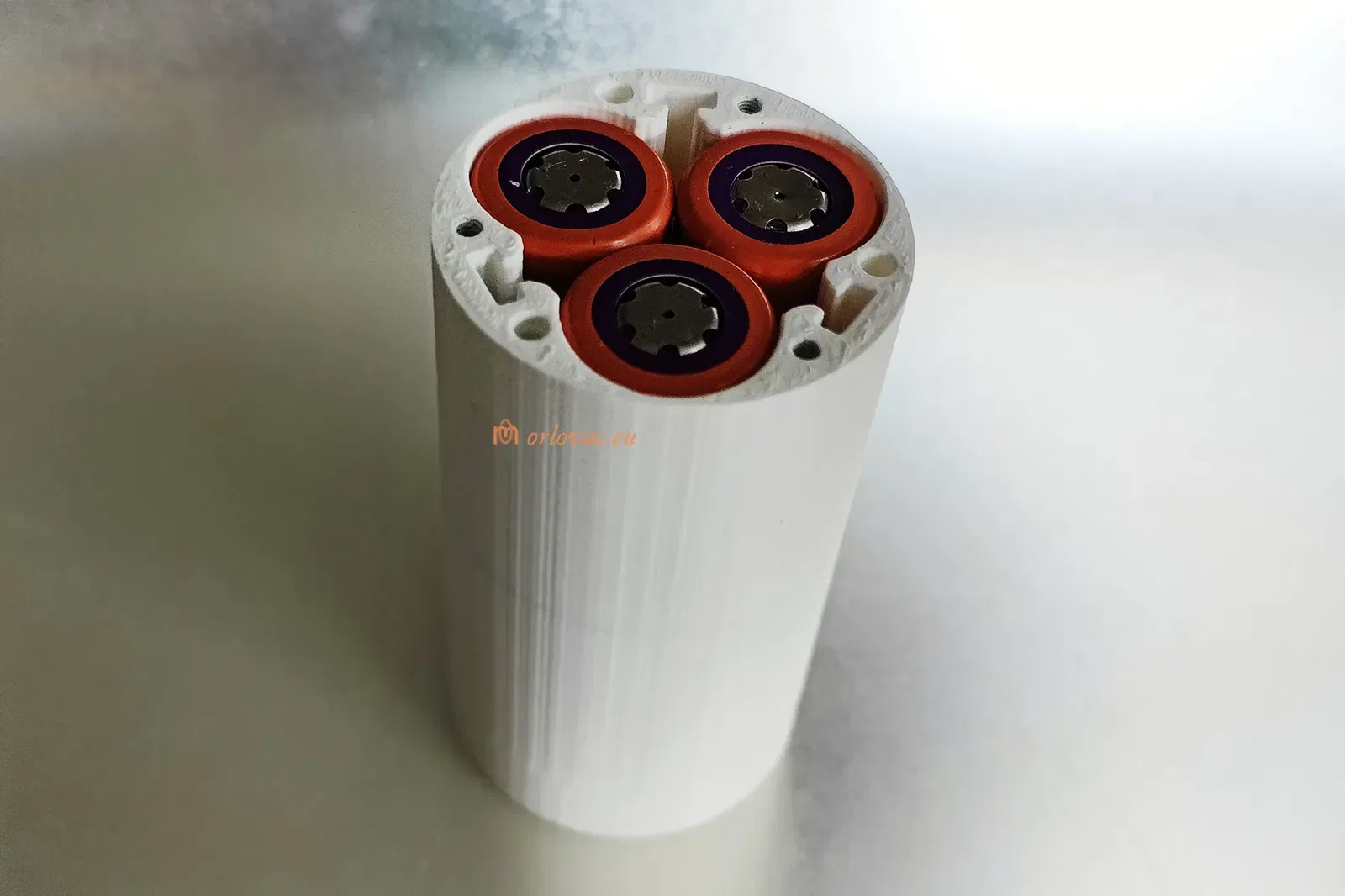
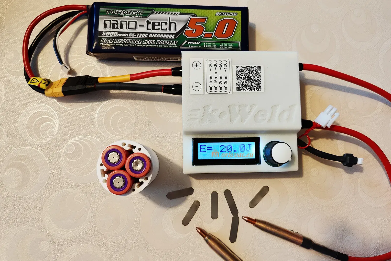
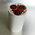
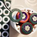
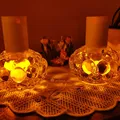
Button batteries are bad idea because of enviromental impact and short burning time. Best options are 18650 Li-ion batteries, but they are too big, until I came with an idea to place such electronic candle upside down. I managed to put three cells in parallell in a holder of DIA 42 mm. When I have tested in a small glass candle holder, I was suprised with effect I got.
I'm very pleased with the result, after two printed examples (so far). Burning time is dependent on each battery capacity. If you use 2000 mAh (3 pcs of the same type), then you may get burning time more than four weeks. Bear in mind, when you charge empty batteries, it may take with onboard charger (500mA) more than 12 hours.
Bill Of Materials:
are specified on the attached pdf drawing.
-
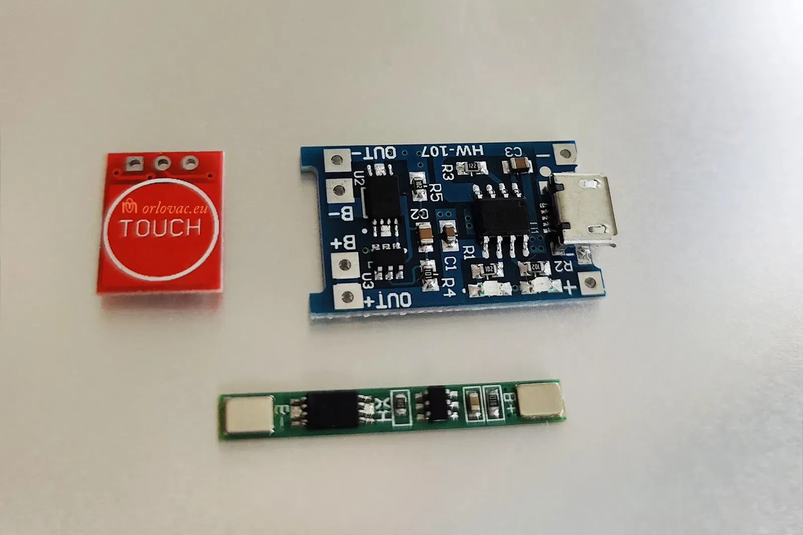
BMS board may be obtained on Aliexpress, searching for: “1S BMS”.
-
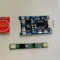
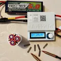
Charging board, on the same place searching for: USB charger module TP4056.
-
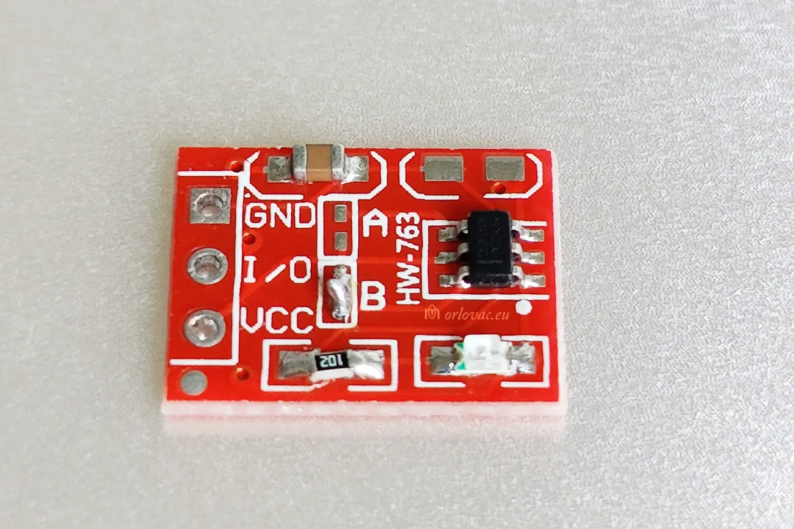
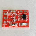
Switch board, search for: TTP223 Touch Button Switch Module.
-
18650 Li-ion battery (3 pcs), you may get it from an old Laptop battery or, for example: here.
-
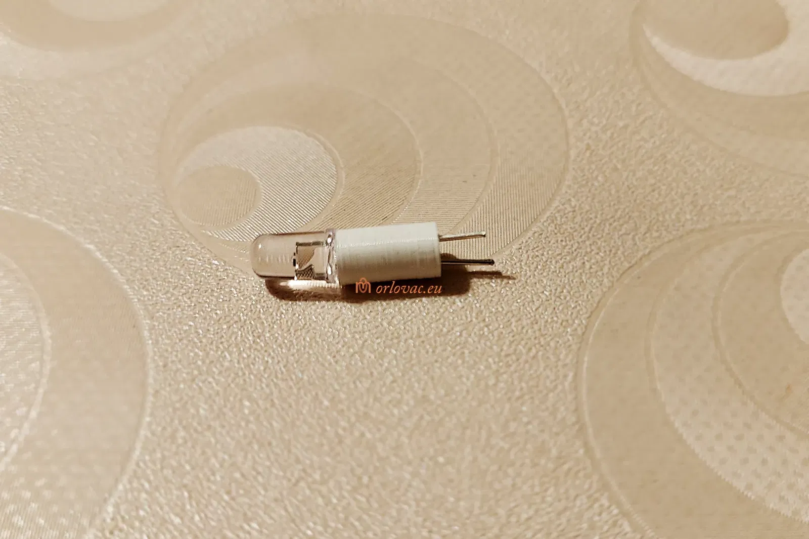
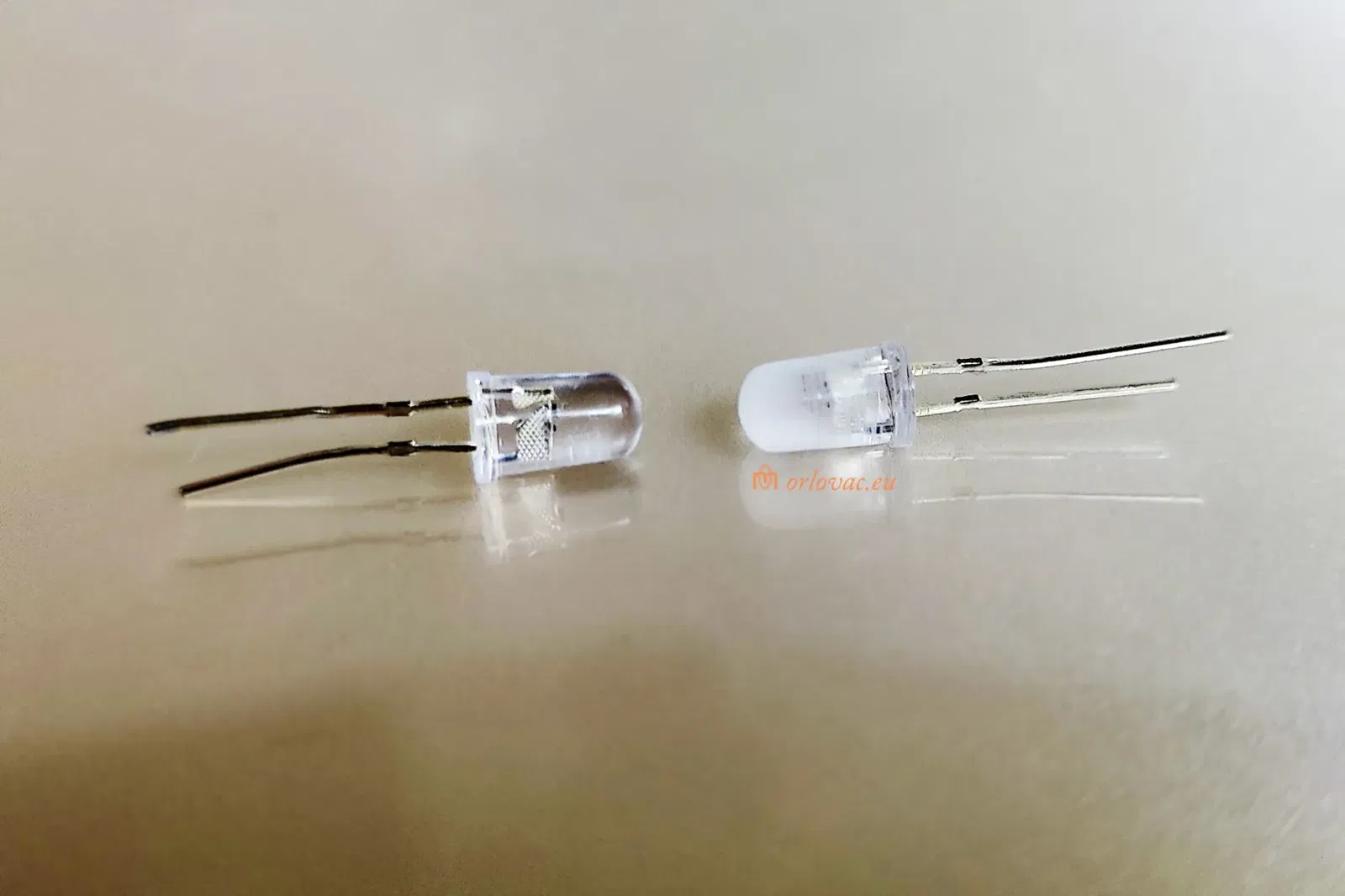
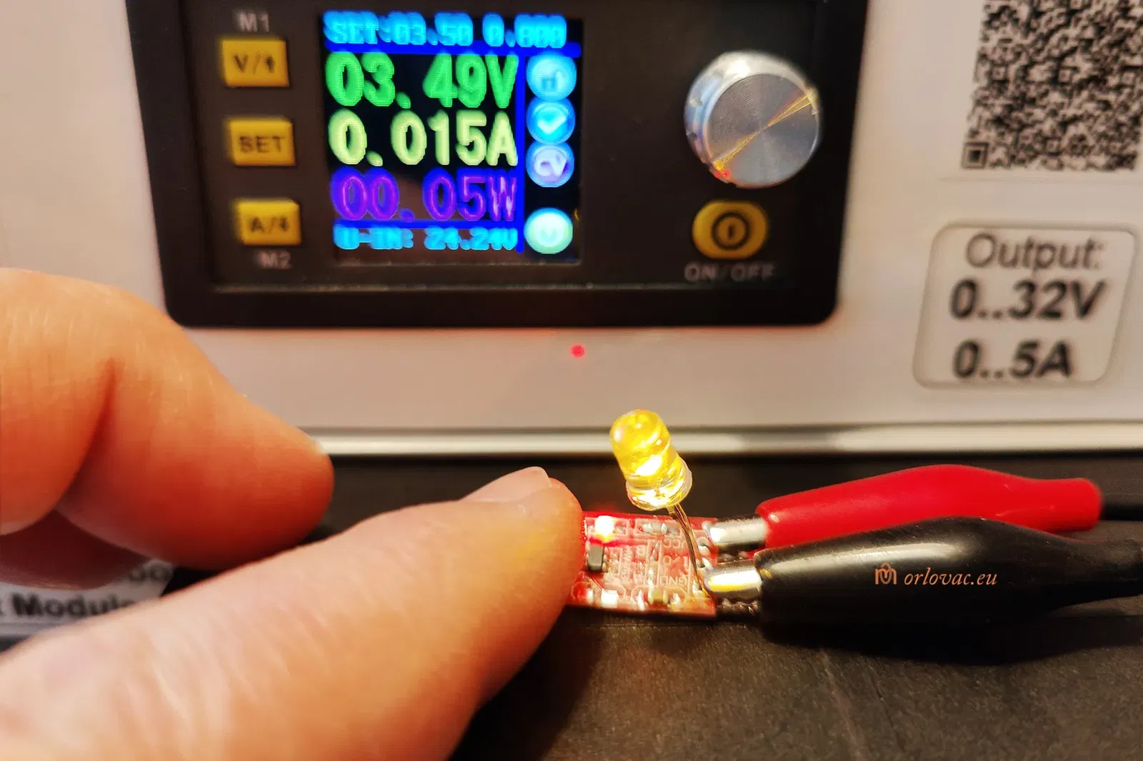
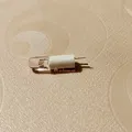
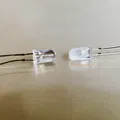
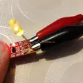
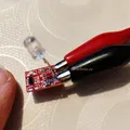
Flickering LED candle, 5mm.
-
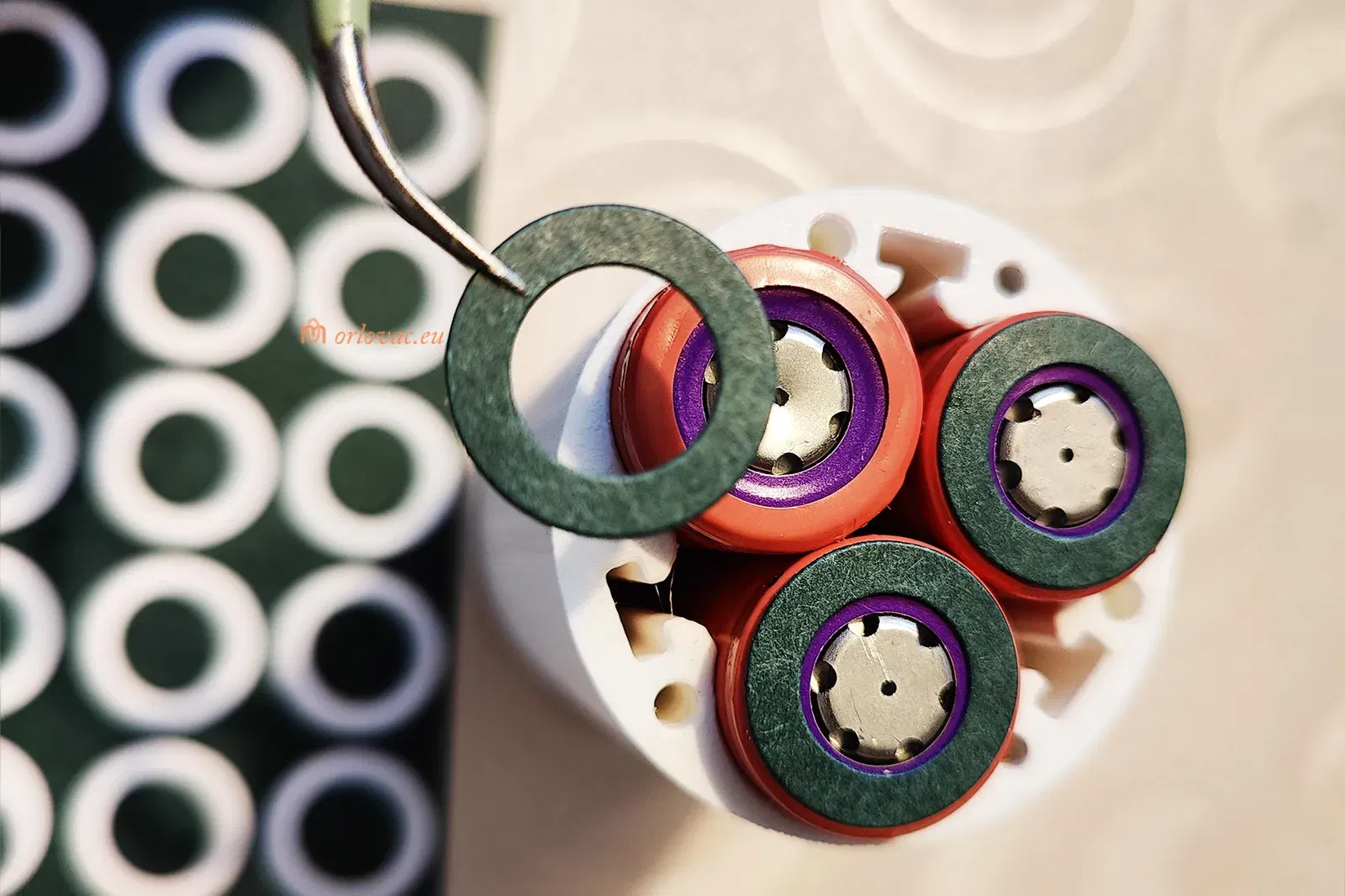
18650 Li-ion Battery Paper Insulation Gasket (x3).
-
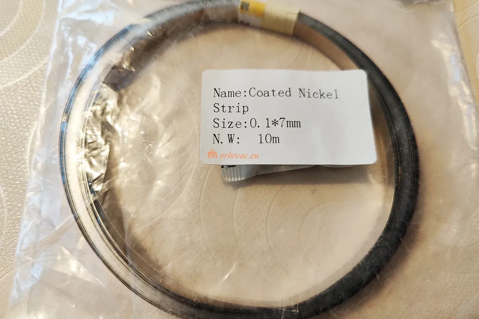
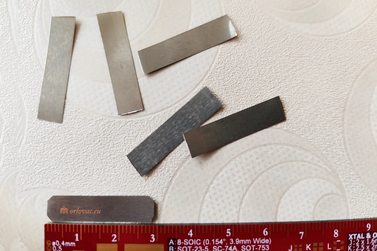
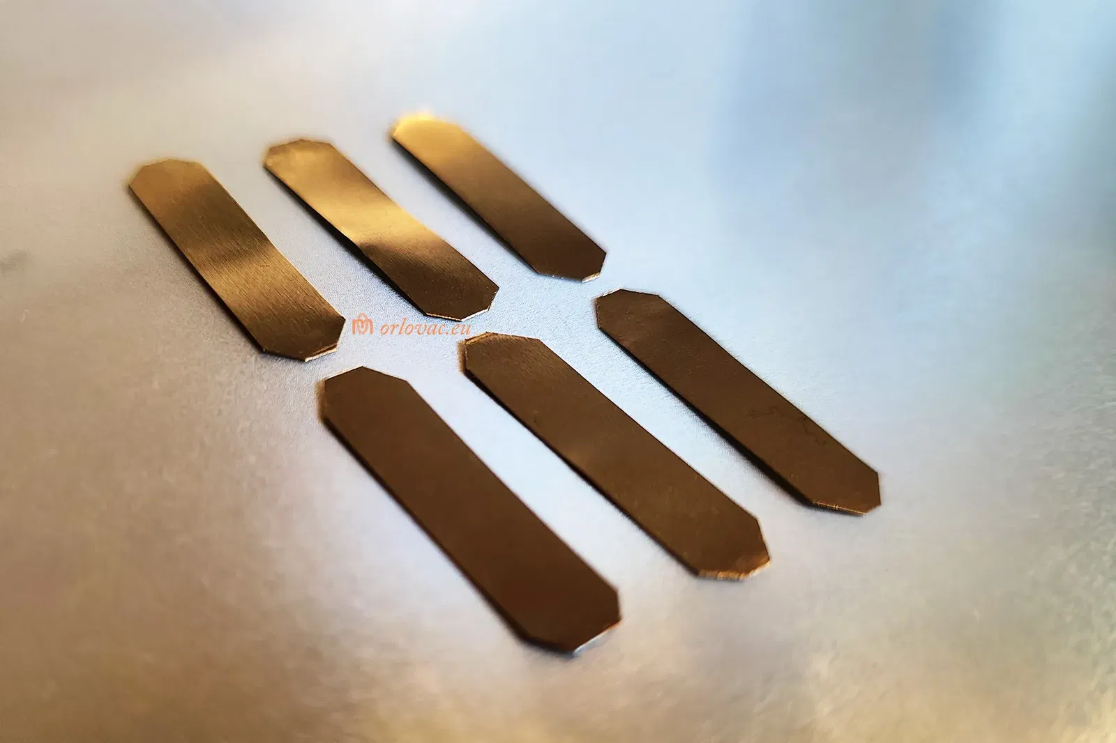
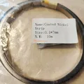
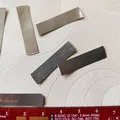
0.1x5 mm 18650 Li-ion Battery Nickel Plated Steel strip.
-
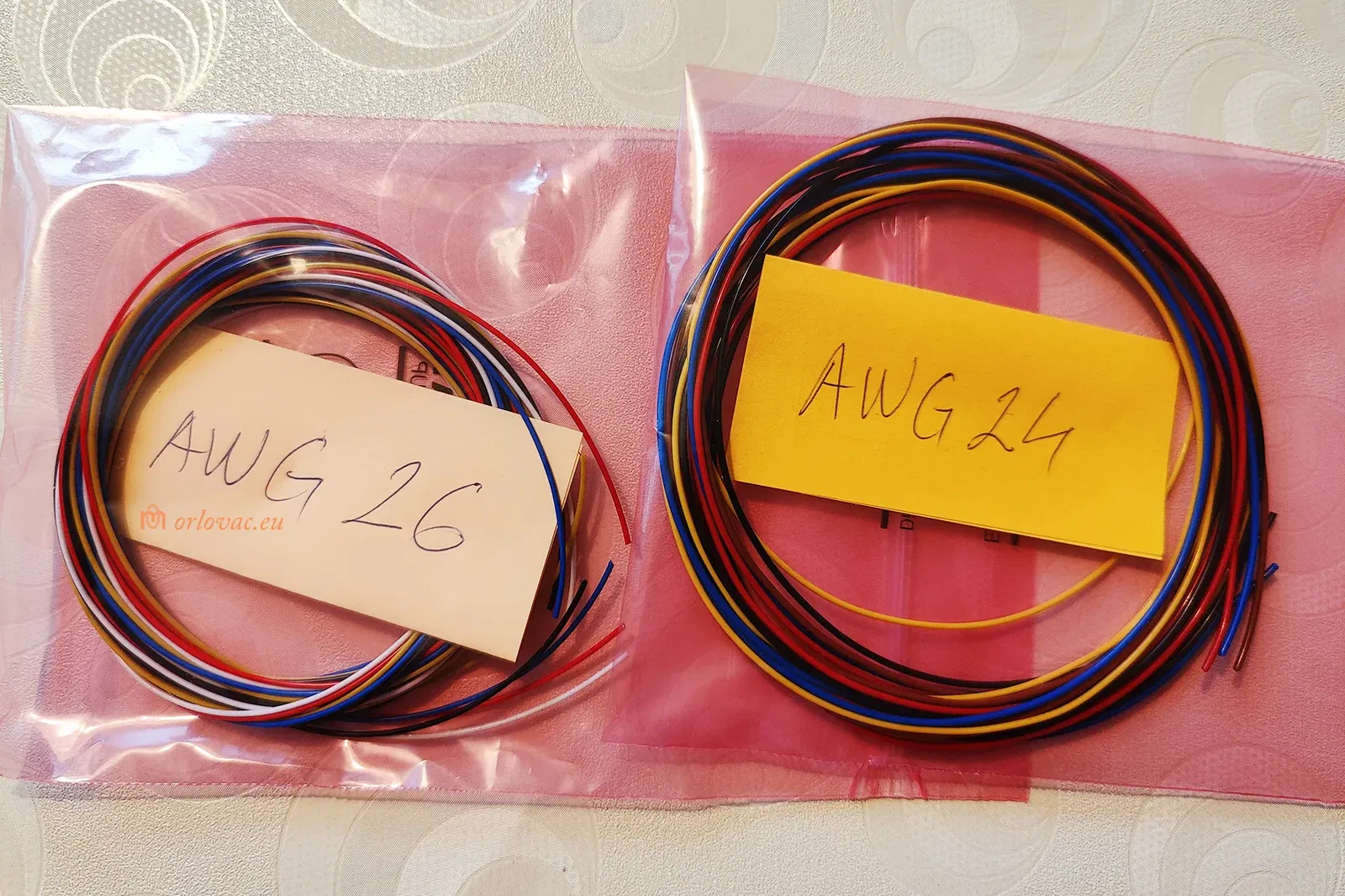
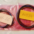
Copper stranded insulated wire, AWG24 for the batteries to BMS and Charger board.
-
Copper stranded insulated wire AWG26-28 for LED and Switch board.
-
M2.5x12 mm screws (#2 * ½").
Assembly Instructions:
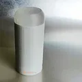
First print all details. White PLA is recommended, except 'Front Part B' would be best if it is translucent, but white may work.
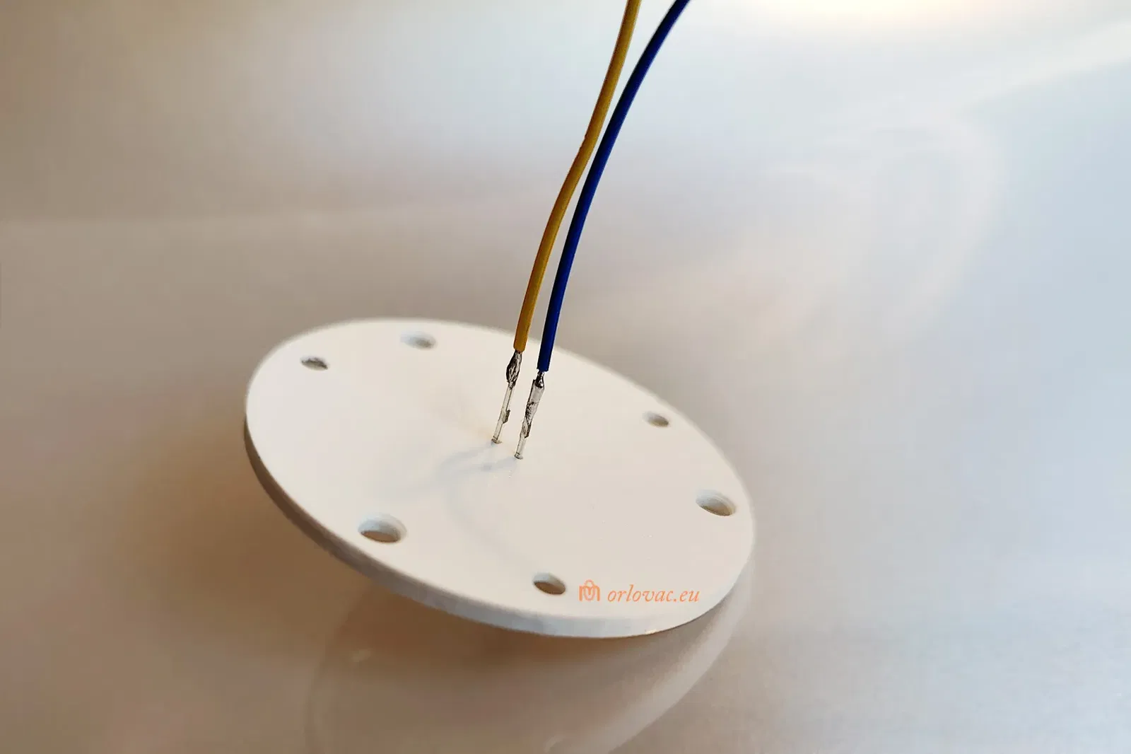
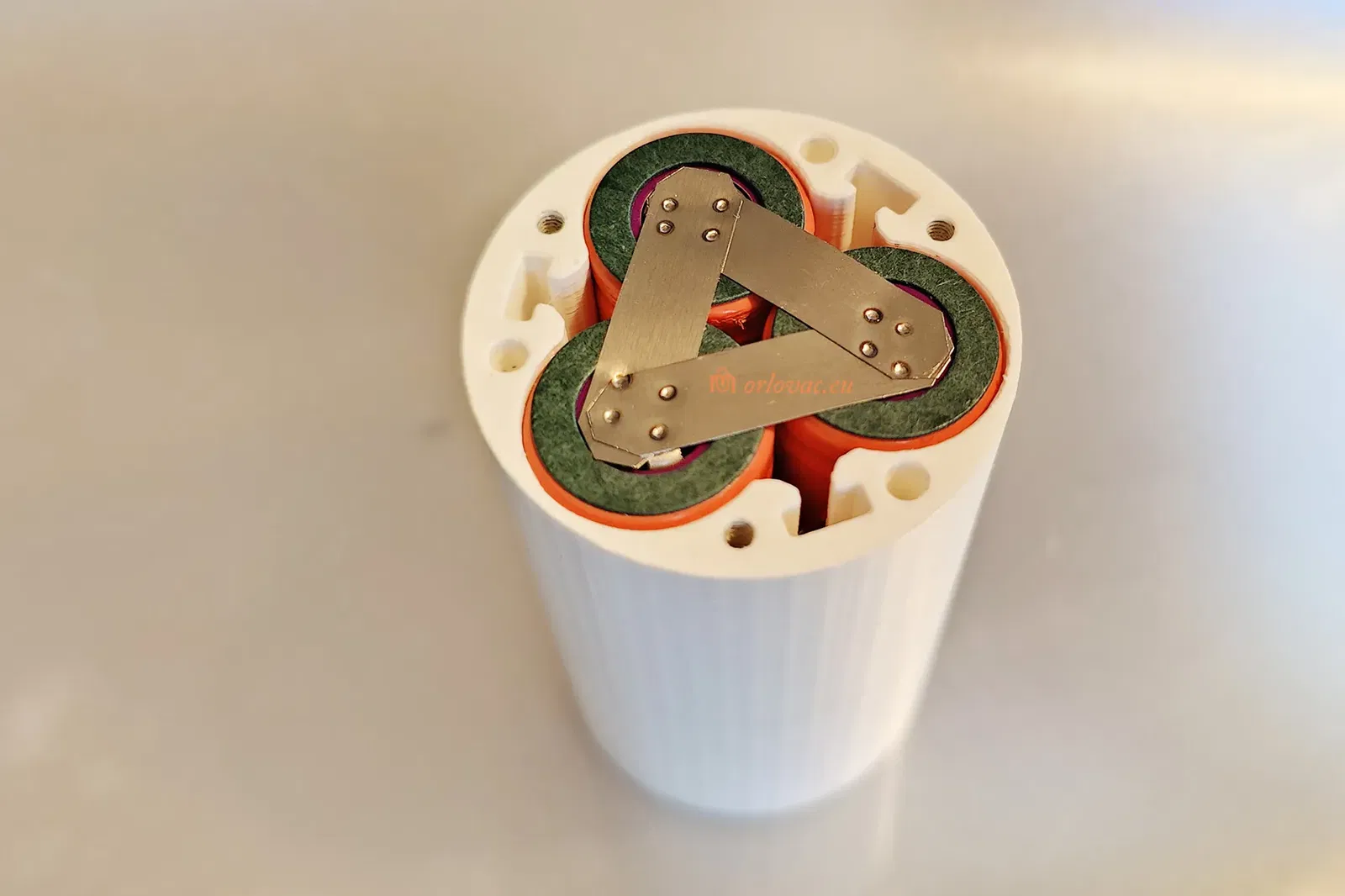
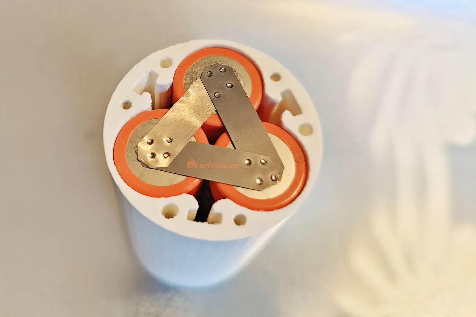
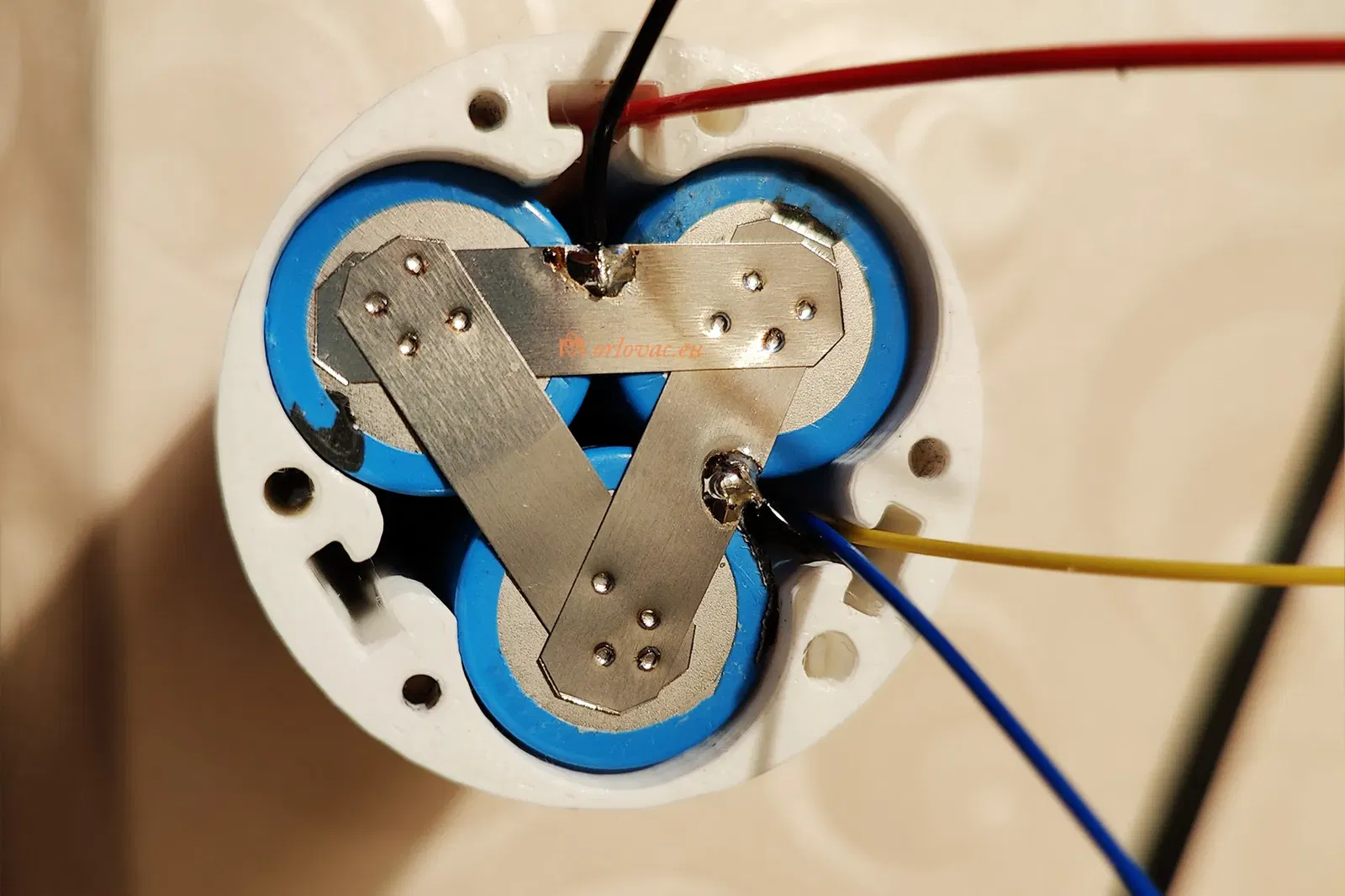
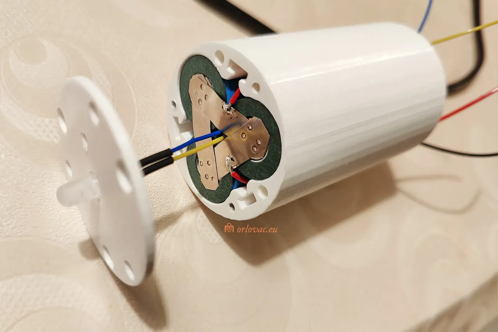
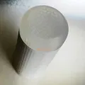
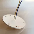
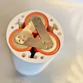
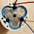
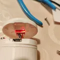
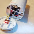
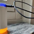
Put three batteries parallellt in the holder and weld nickel strip according the provided pictures, both on Plus and Minus terminal. I strongly suggest to use paper insulation Gasket only on plus terminal. Do not solder strip on bateries, but weld it, then you can solder on the strip only!
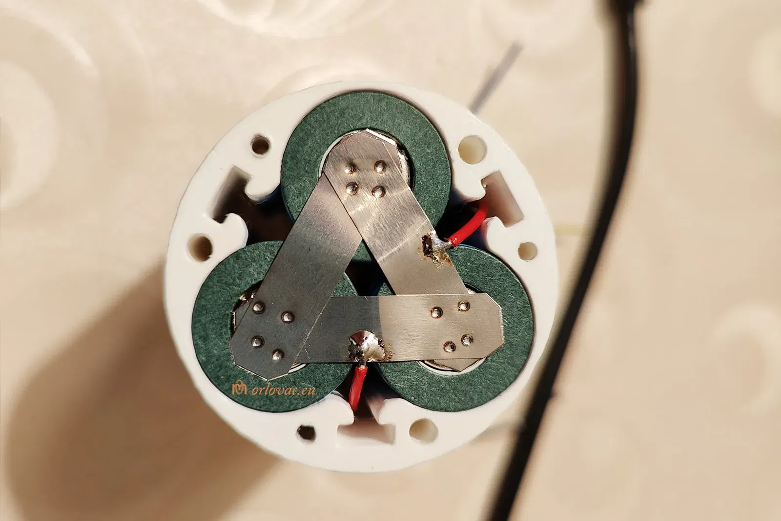
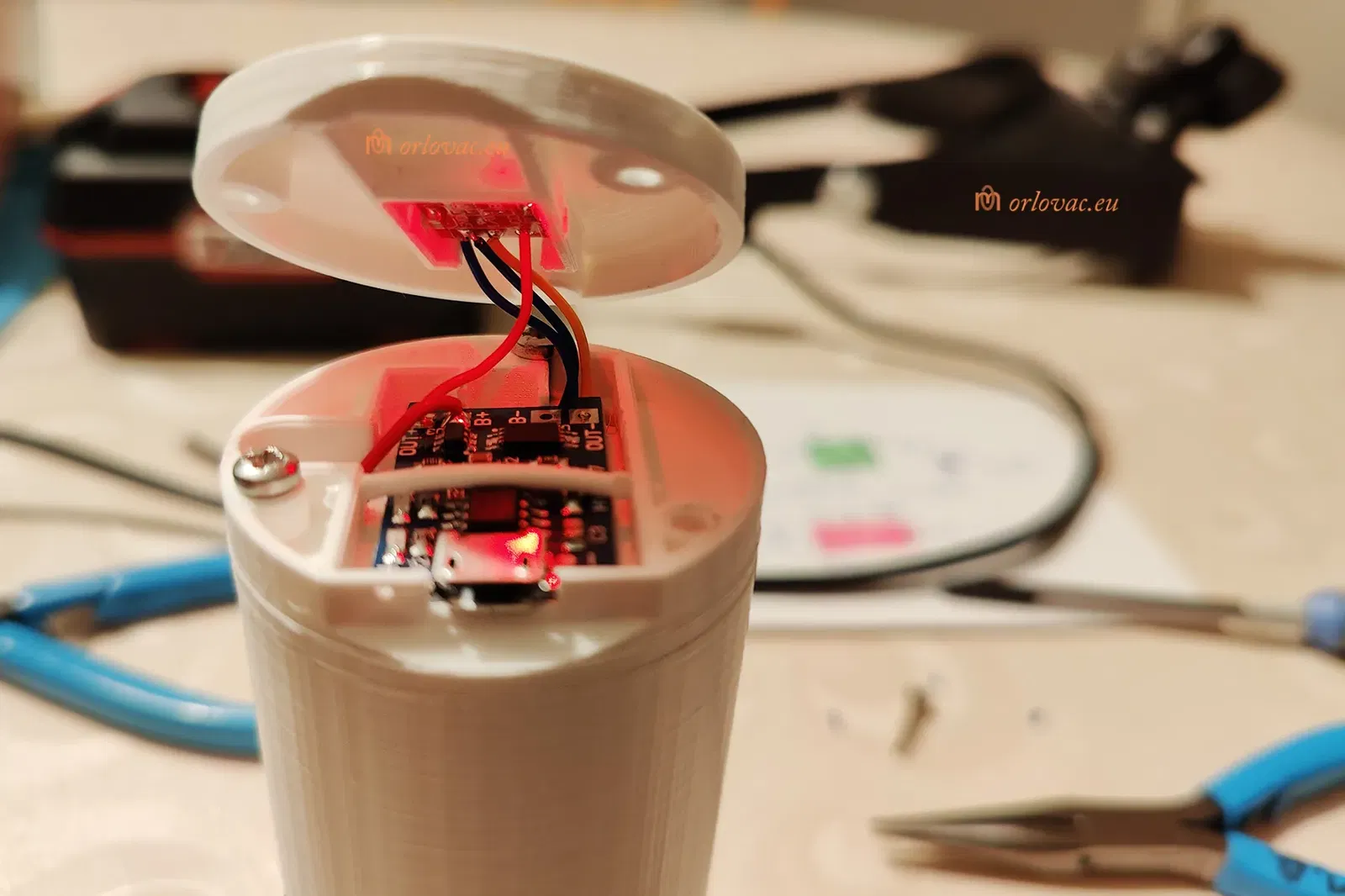
Solder a bit of AWG24 red wire on Plus terminal and to BMS B+; same gauge of black wire, need to be soldered on Minus terminal and BMS B-. Additional wires of the same gauge is needed to be connected dirctly to the Charger Board: Red for + and Black for -.
From the BMS board, use AWG26(28) wires: P+ red to Touch board +Vcc; P- blue to the same board GND. For the LED: Anode, yellow and Cathode, blue, will be soldered onto the Switch Board, according to the schematic diagram.
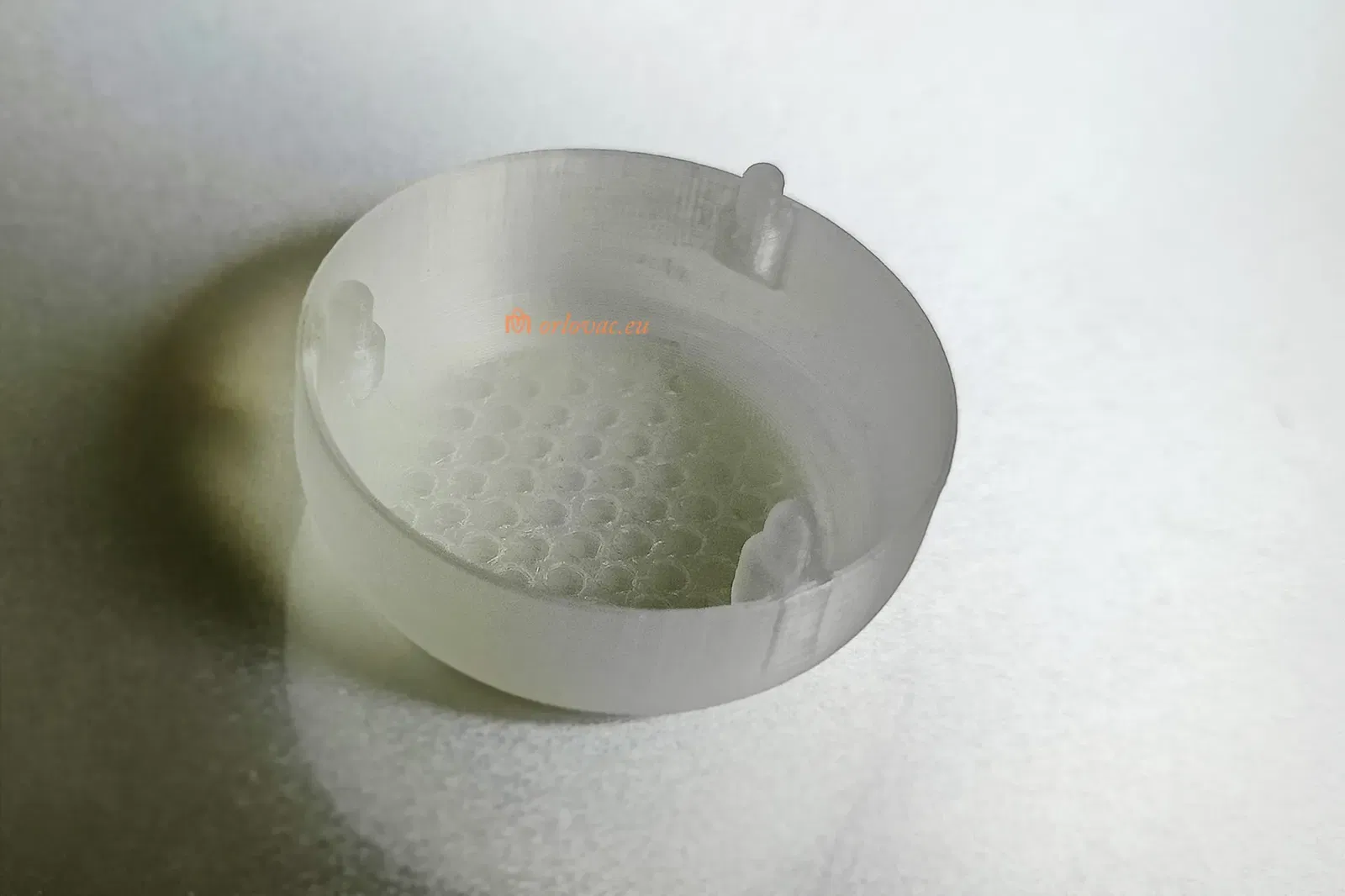
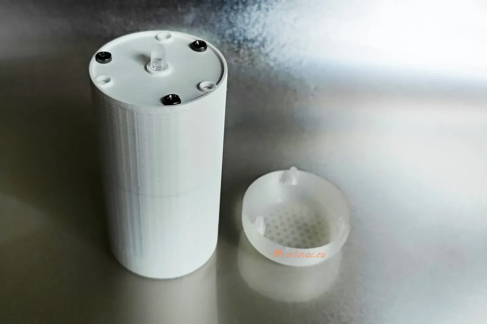
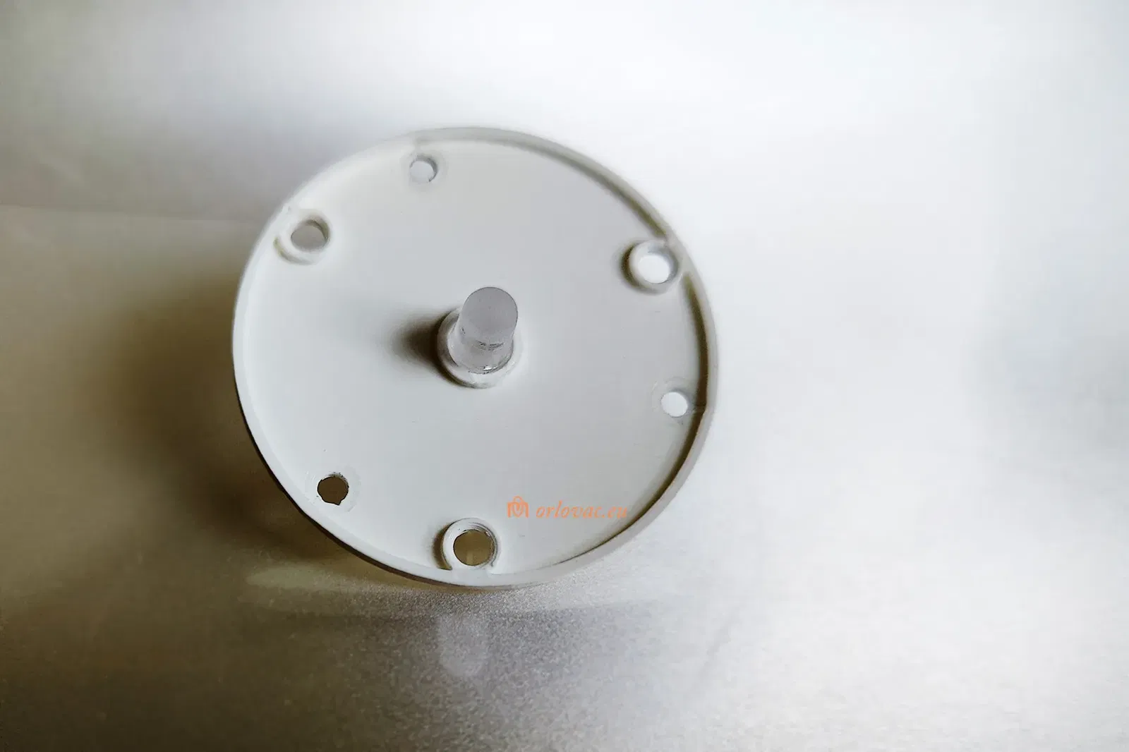
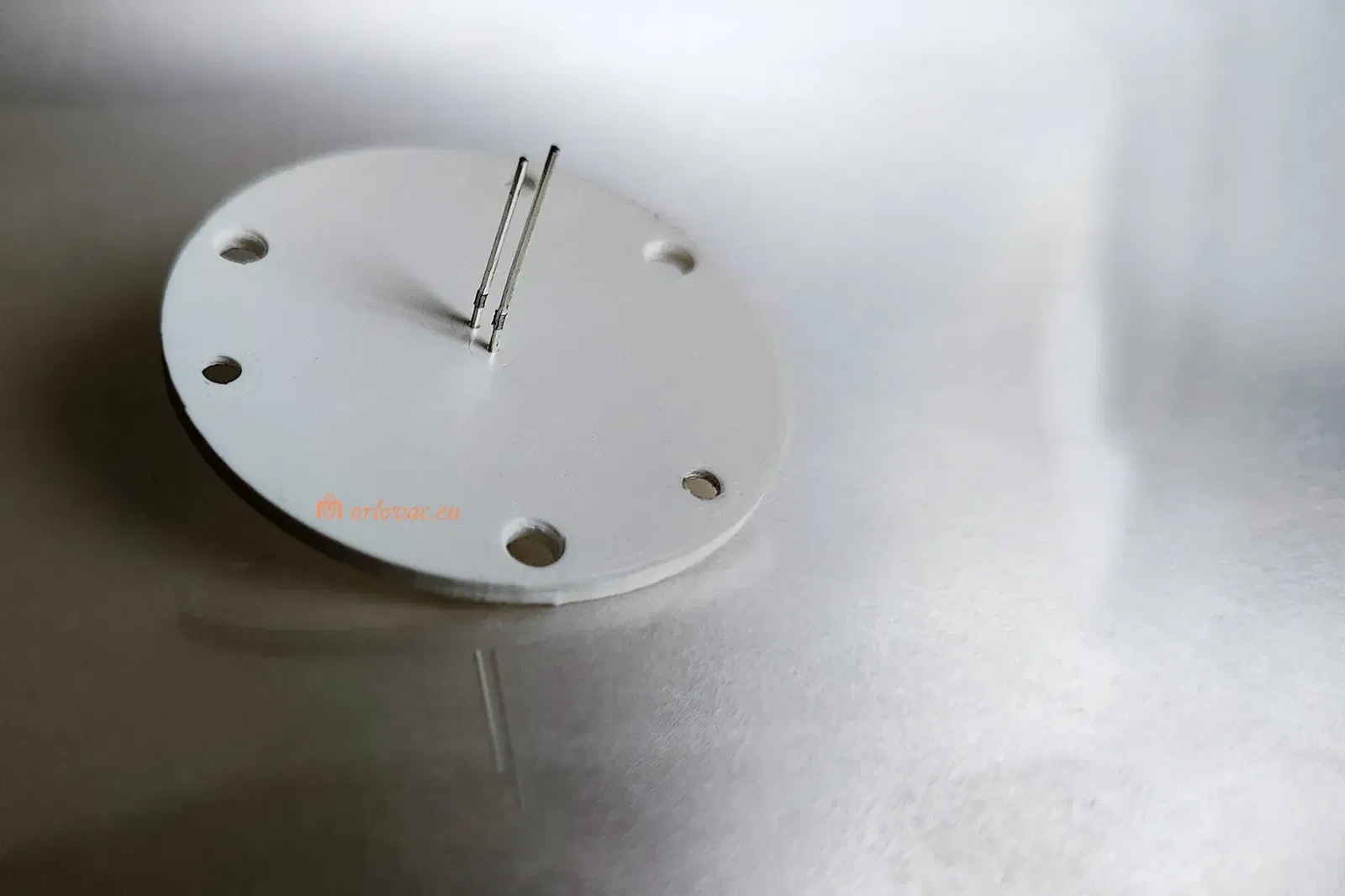
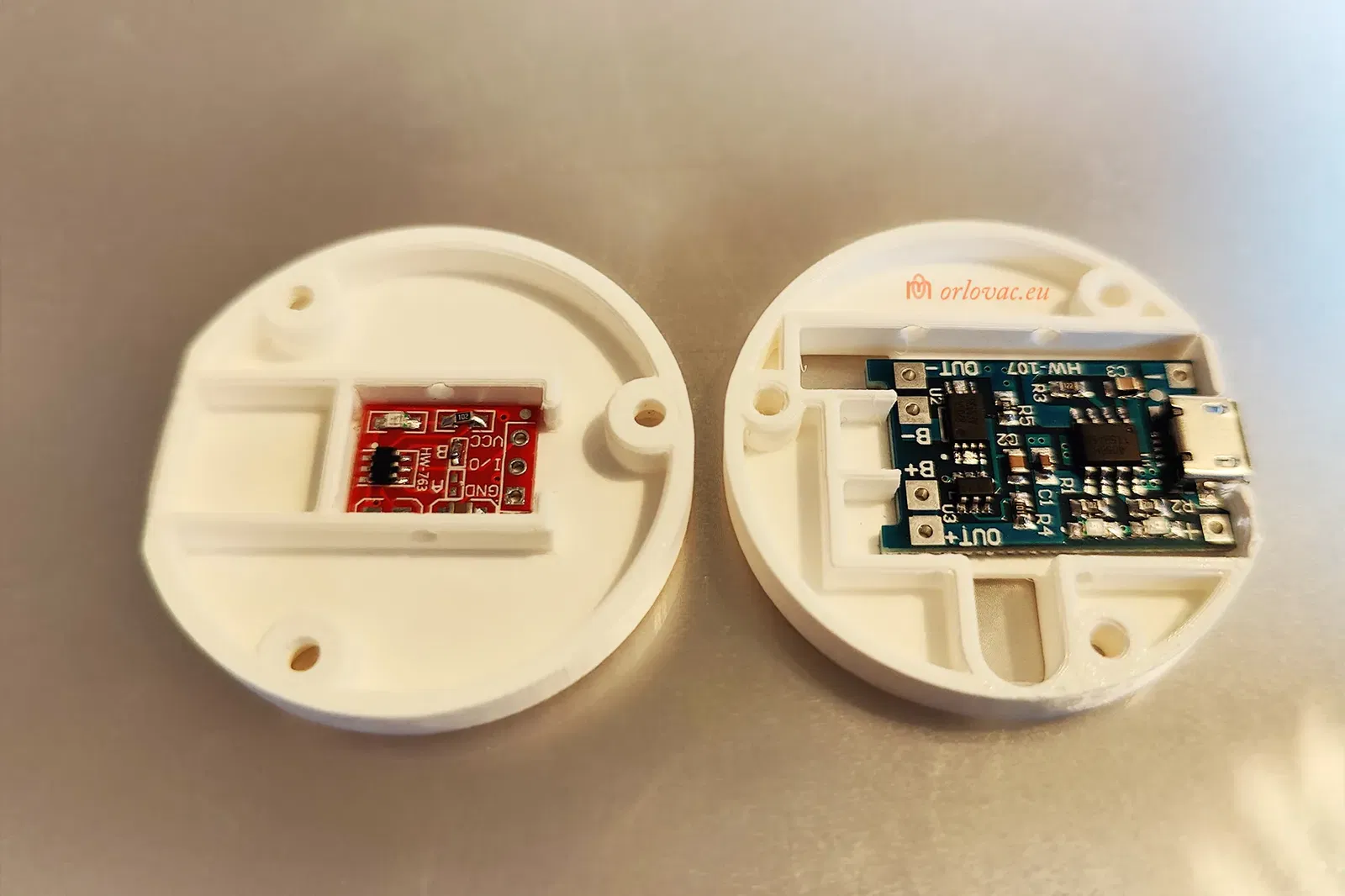
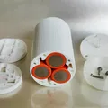
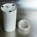
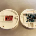
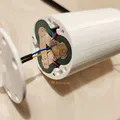
Insert batteries and the BMS in the printed ‘Battery Holder’. Place the LED into ‘Front Part A’. You can use quick glue if necessary. Soldering need to be insulated by help of shrink tubes. Place ‘Front Part A’ on the ‘Battery Holder’ and fit it with three screws.
Now is time to work on the rear part.
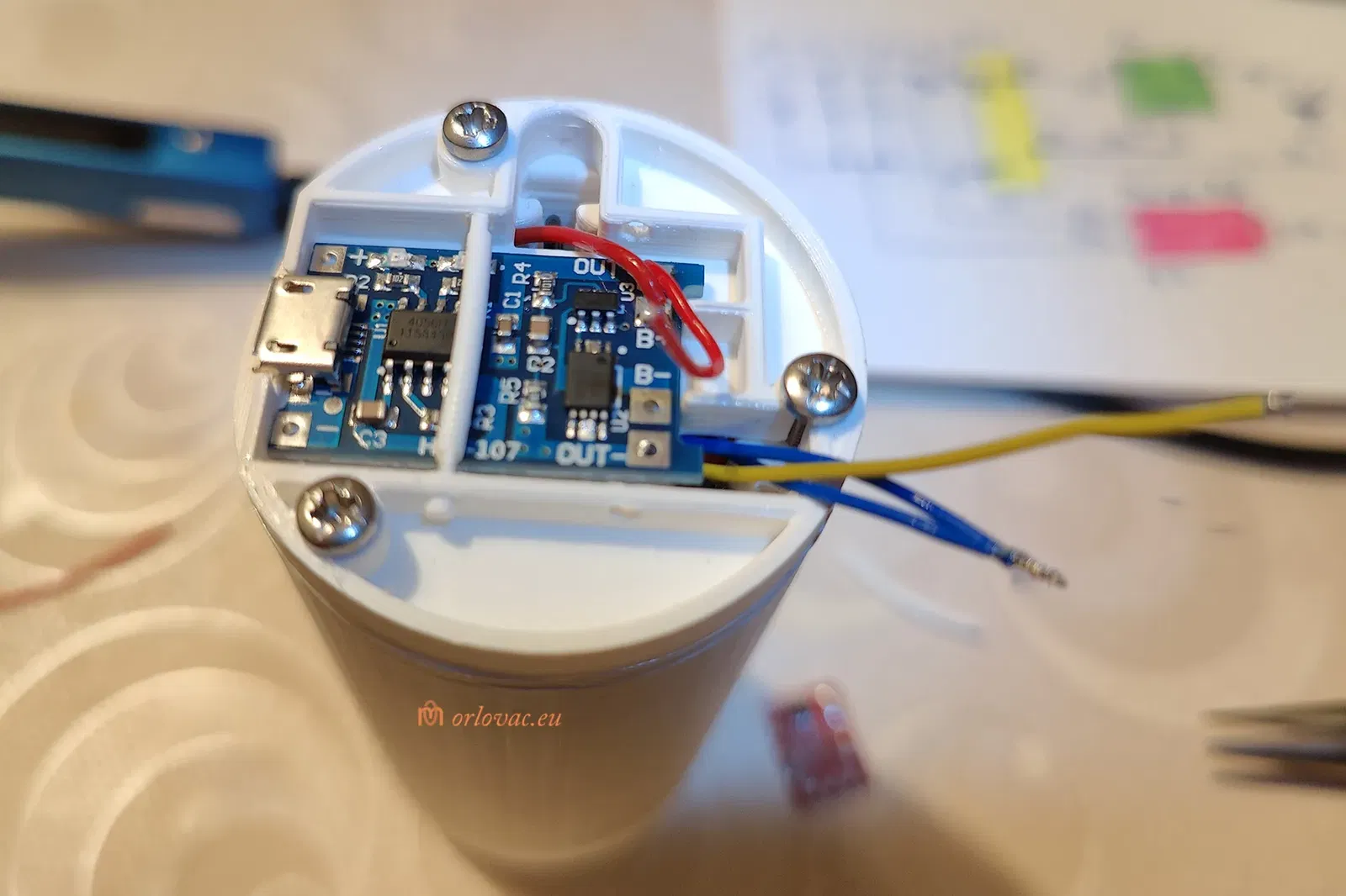
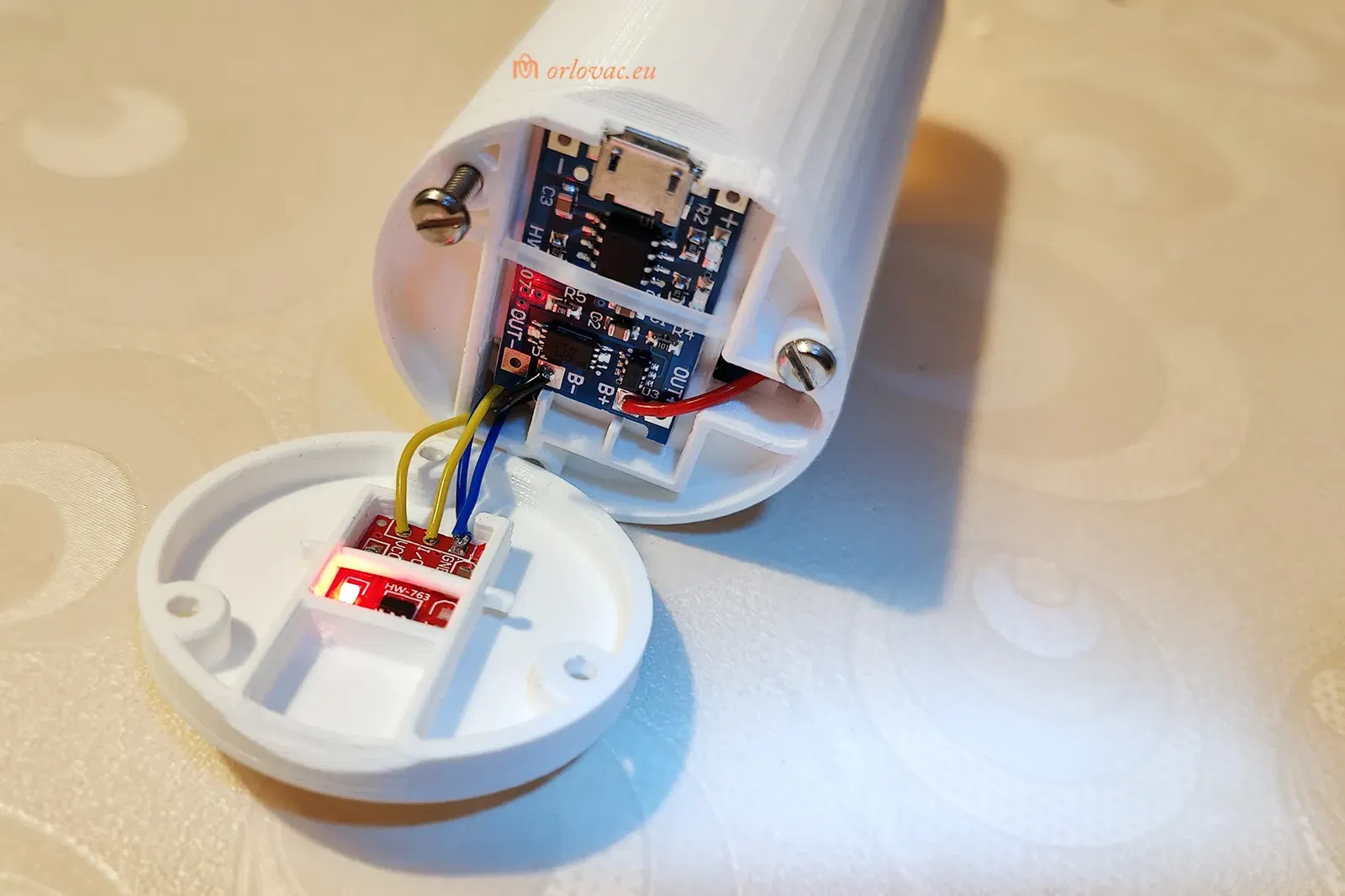
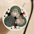
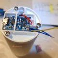
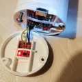
Place the Charger board in ‘Rear Part A’, and place all wires through this part's holes. You may temporaryly fix this part by help of two screws. Cut AWG24 wires to the Charger (one by one only!) and solder them on the Charger board: red on B+, black on B-. Put a bit of print filament over the board to secure it on its place.
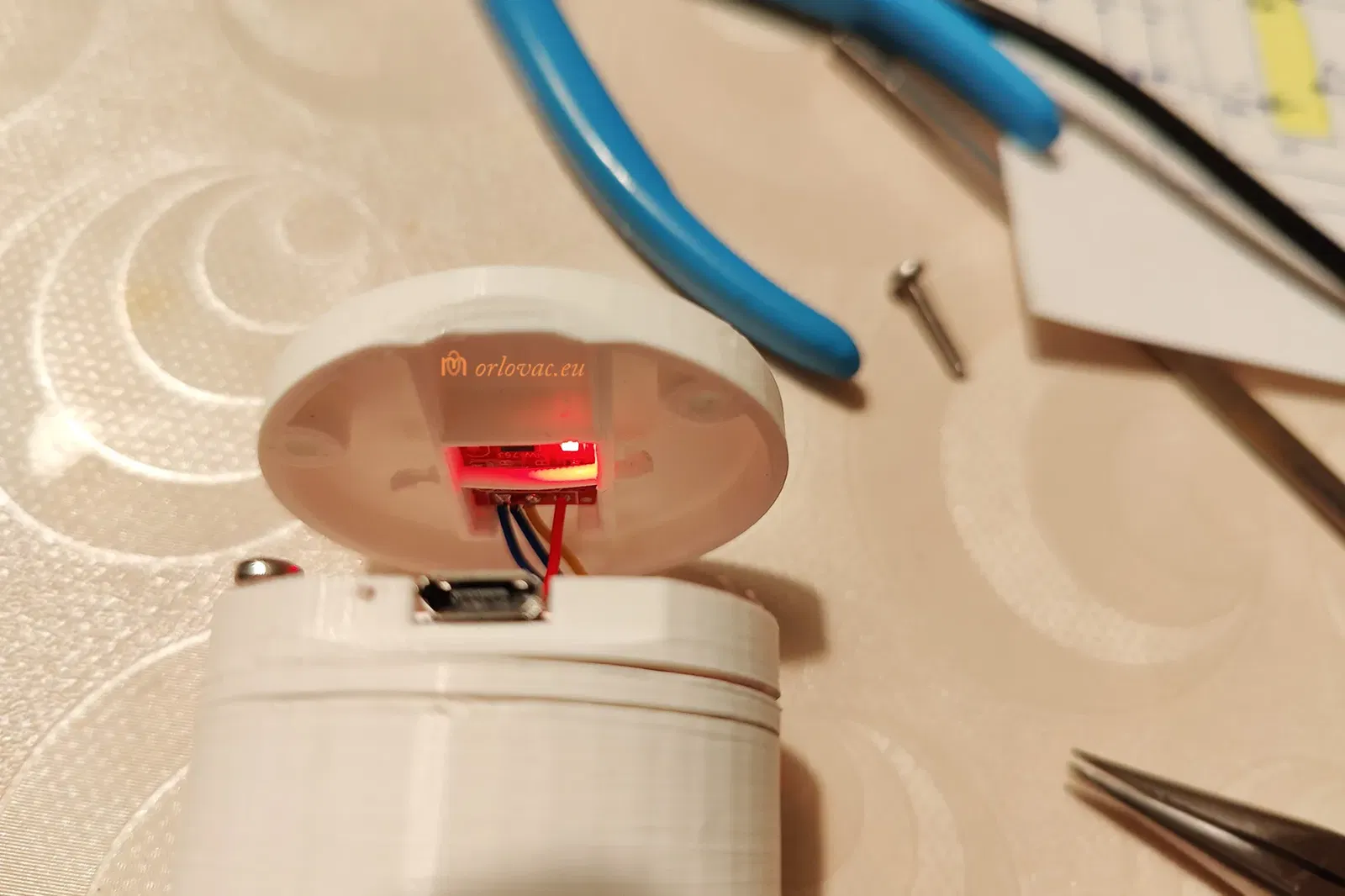
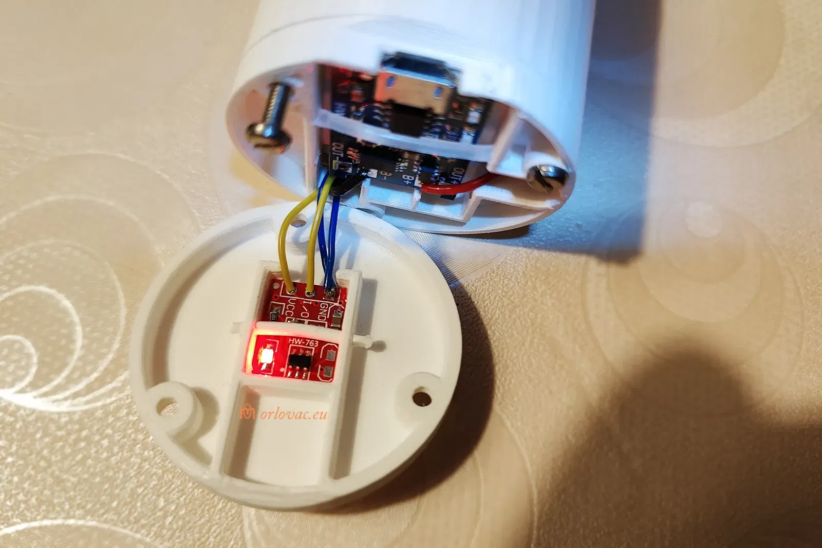
On the Touch Board, solder two blue wires (one from LED Cathode and another from BMS, P-) AWG26(28) to GND. Red from BMS P+ to Vcc; yellow from LED Anode to I/O. Press this board into its place in ‘Rear Part B’ and secure it with a bit of print filament.
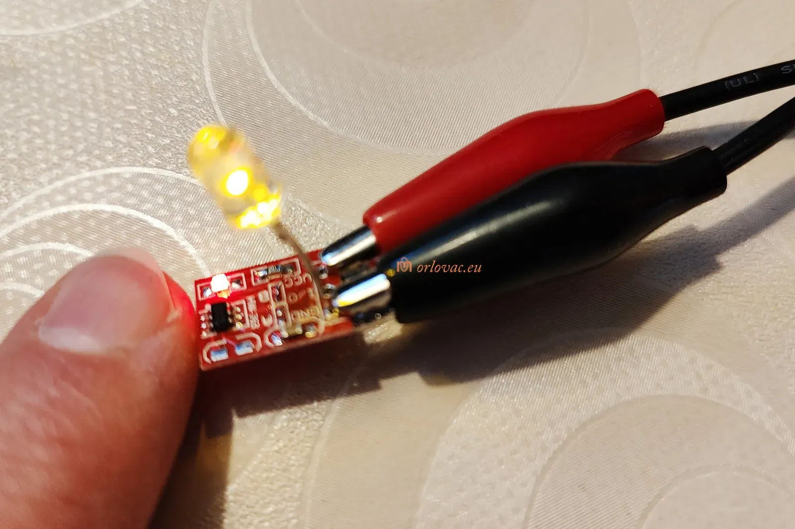
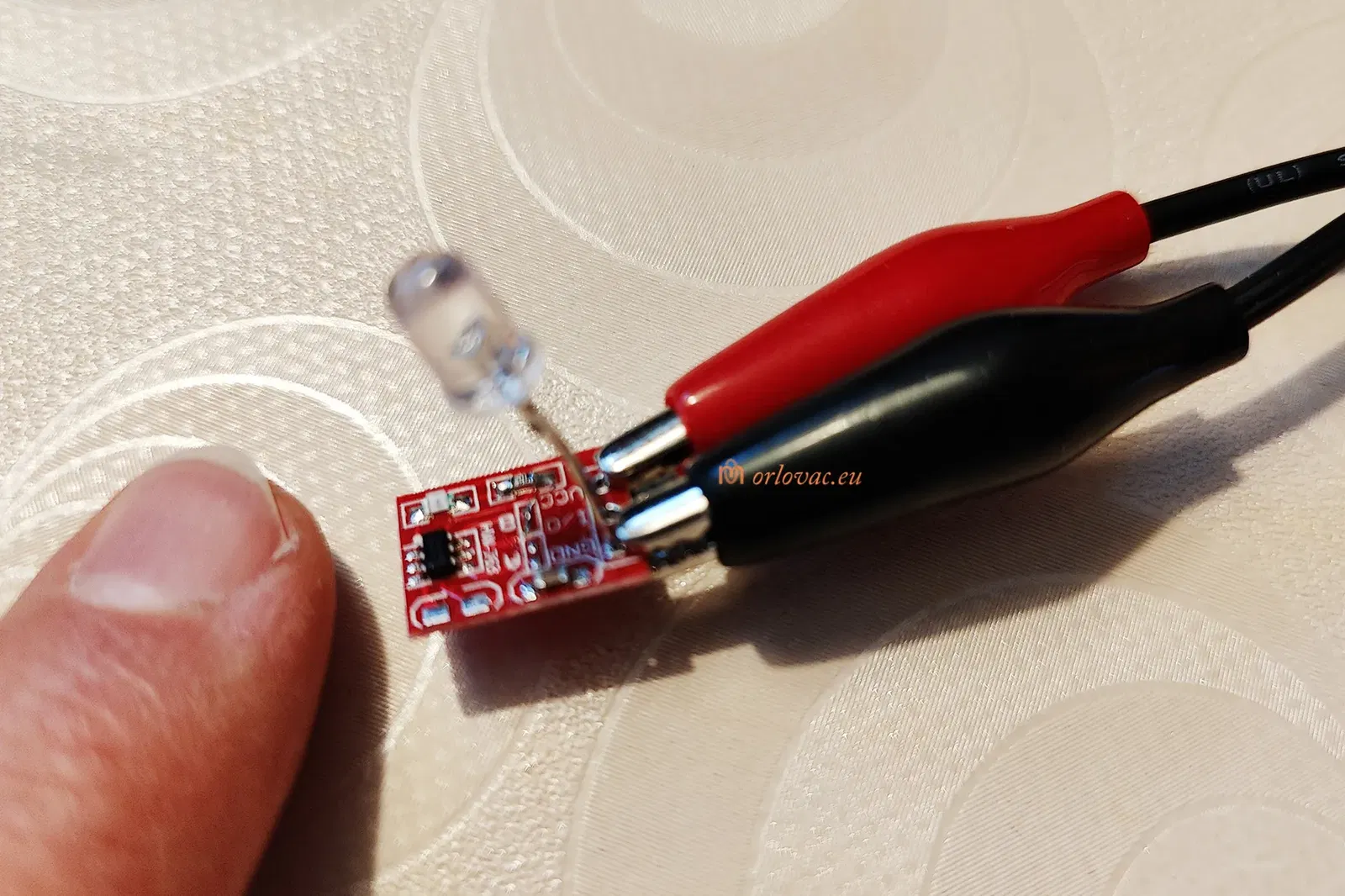
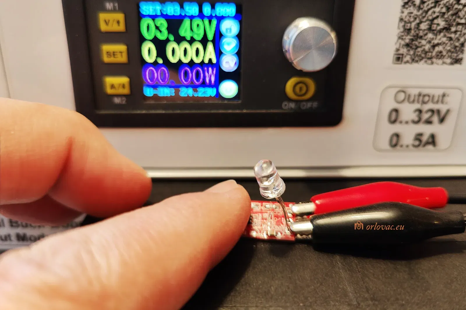
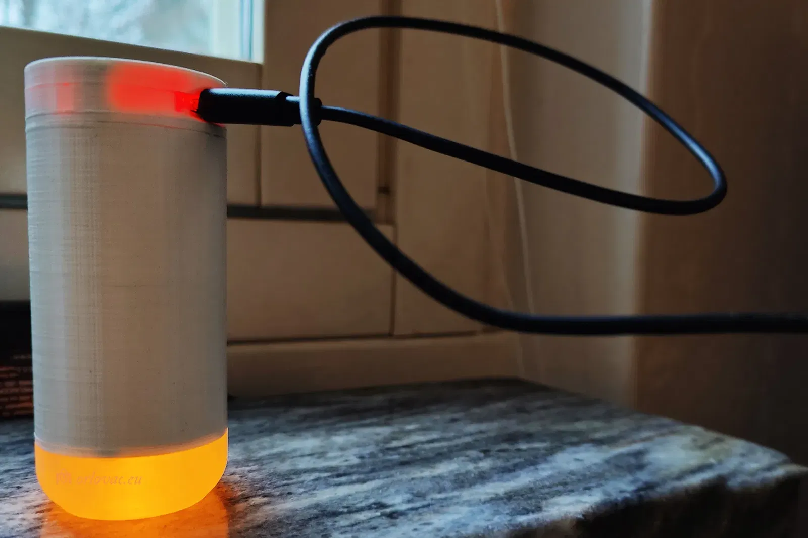
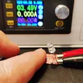
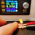
Prior to fitting all rear screw, you can test if everithing works fine: finger to Touch area should turn the LED on. Touch again and the LED will turn off. Put Micro USB carger to USB port and test charging. The red light should lit indicating ongoing charging. Now is time to place and tighten all rear screws.
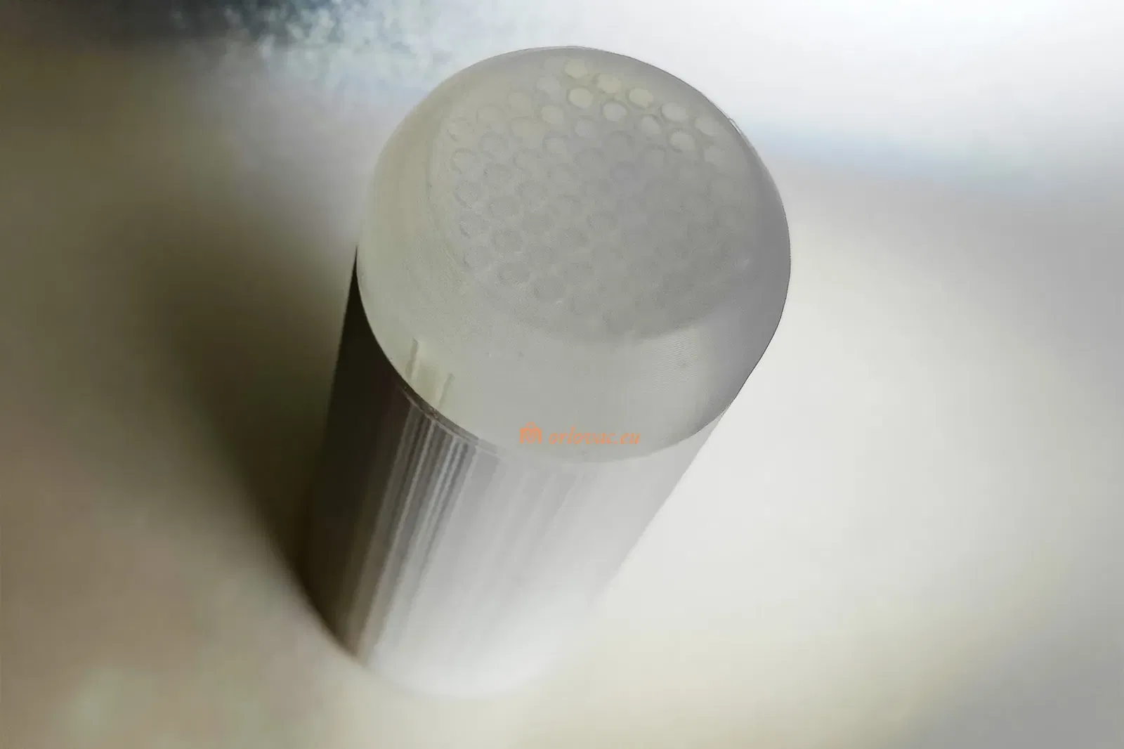
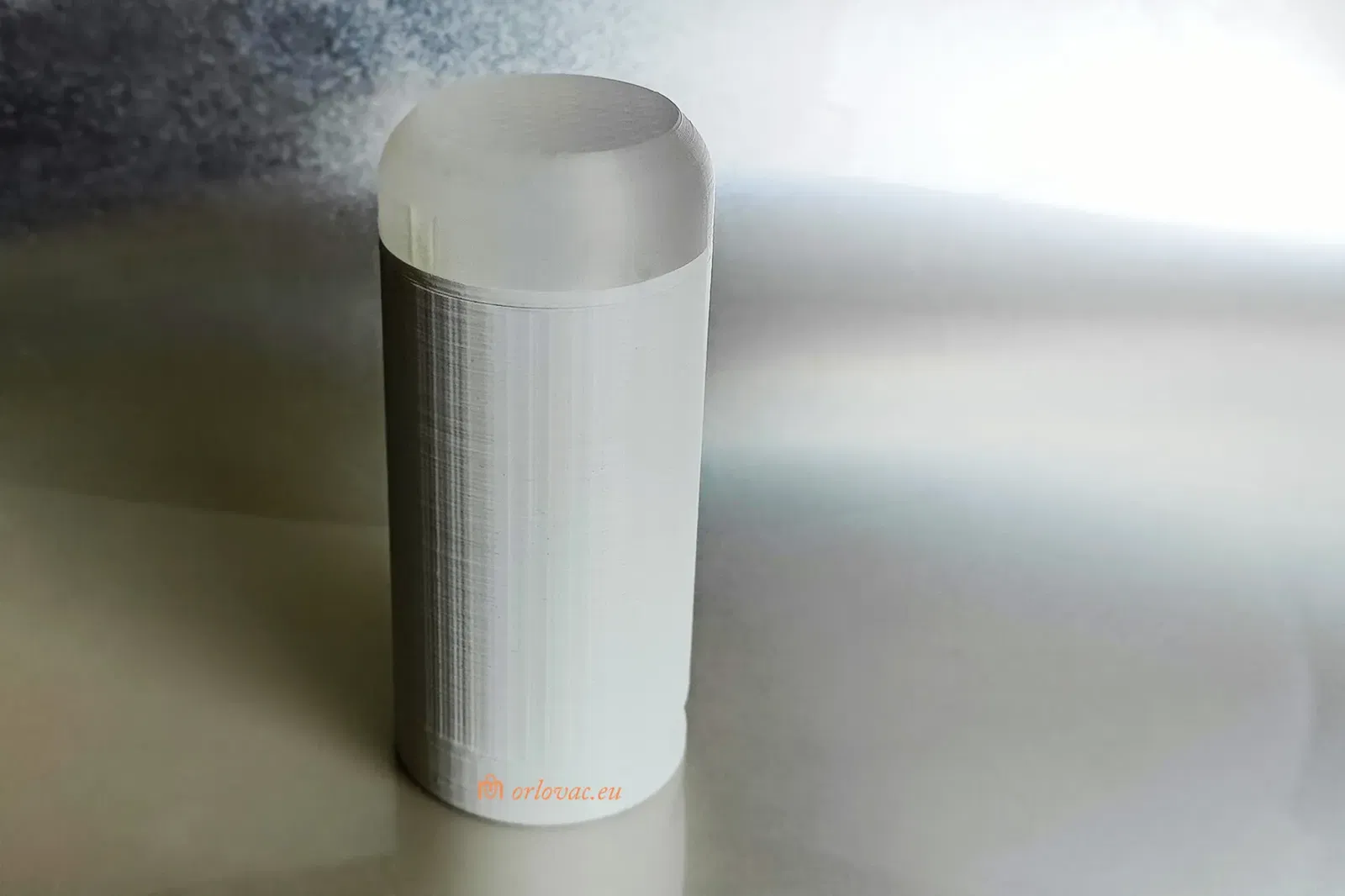
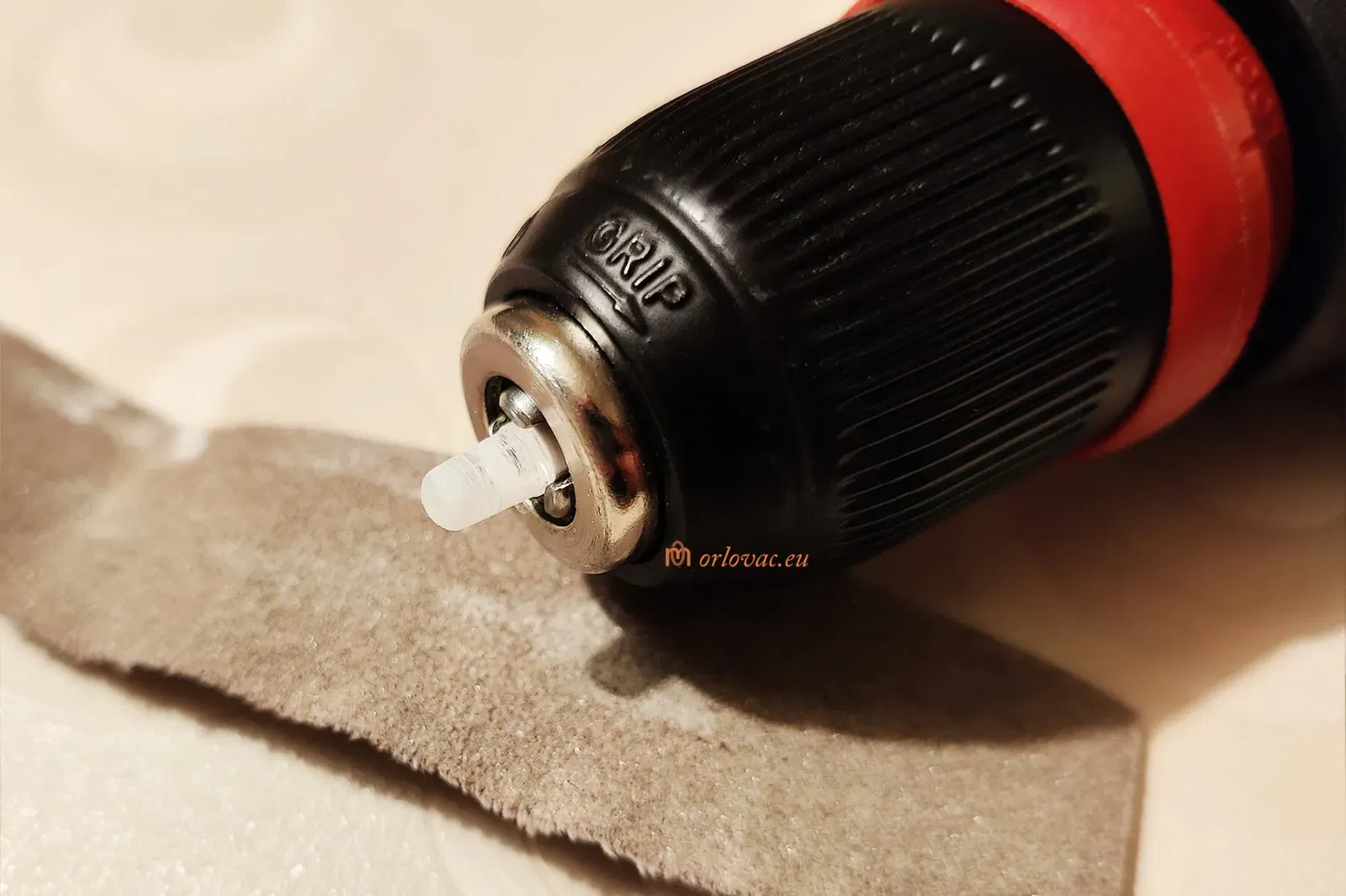
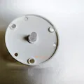
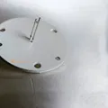
Now place ‘Front Part B’ into its place. If it doesn't fit well, use a bit of sand paper to shape three pins, to get them fitting tightly into the Battery Holder’s 3mm holes.
The leakage current for Touch board is quite low and may not be enough to keep batteries charged during unused period of one year. This need to be tested. If this candle is not used, charge it twice a year.
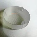
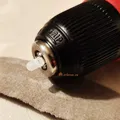
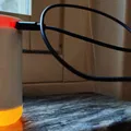
The drill LED holder is optional and helps to keep a LED in the chuck while you are sending the LED's surface to get it dull for better light dispersion.
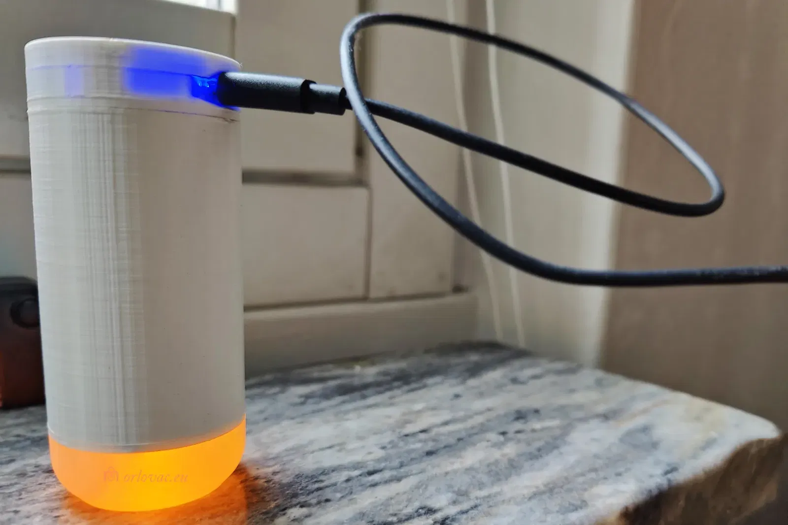
When carging is finished, blue light will indicate it.
Giấy phép

File mô hình


Chưa có bản in nào được khoe. Hãy là người đầu tiên!

Chưa có bình luận nào. Hãy là người đầu tiên!