Raspberry Pi Pico ADXL345 Case

Fancy và khó in trường hợp cho một bản sao Pi Pico và Estardyn bằng một cái búng tay trên nắp và giảm căng cho một con mèo 5E
Mô tả
This is unnecessarily fancy for a simple Pico case, but it is very robust and works well if you can print it.
This is based on the tutorial for Raspberry Pi Pico Case design in Fusion 360 by Kevin McAleer on YouTube, link to video -
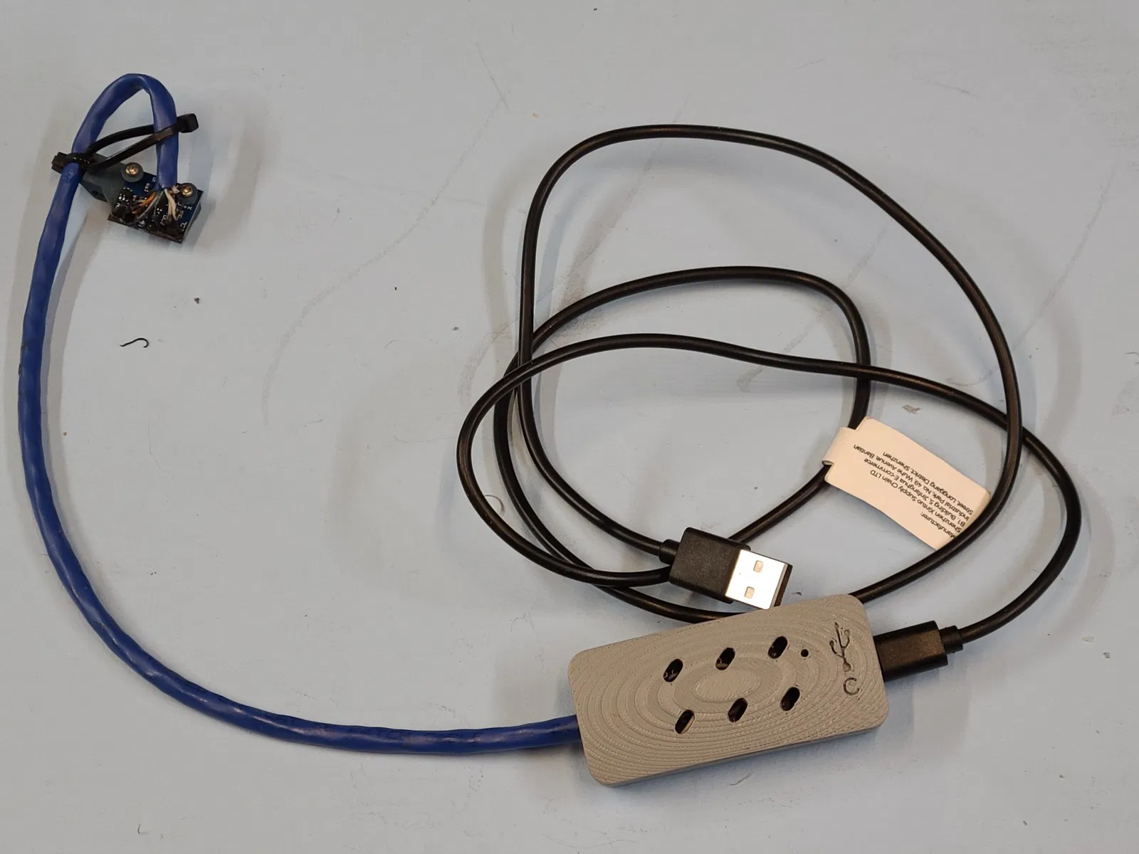
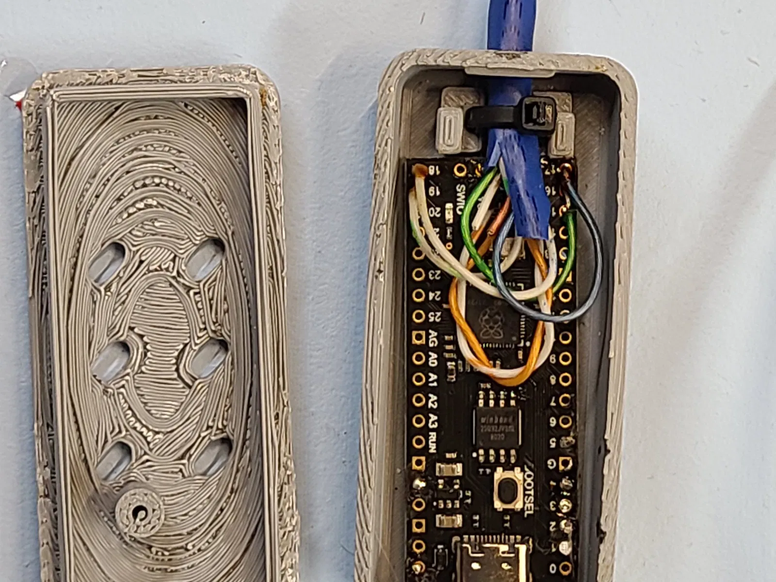
This is a really nice tutorial about making somewhat organic shapes in Fusion 360, but the model he designs is pretty basic. I added extras like the strain relief for the Cat 5e cable (in my case to connect the ADXL accelerometer), boot button access, fillets, completely reworked the snap latch so it would actually work and not break, added clearance between the top and bottom, cooling vents, etc. My intent was to use an Aliexpress clone Pico that I got to check out. What I found out was that it does not match the Pico form factor and does not have any mounting holes. So I have included two versions, one that should fit the real Pico and the other that works with a 21mm x 53.75 mm x 1.5 mm board with no mounting holes. The model posted here for the clone has some additional improvements over the one in the photos to hold the board more securely. I just don't want to try to re-solder it again since what I built works. I included a C on the clone case because it comes with a USB C connector. The one for the real Pico has posts that I intended to melt down to hold the board once it was all soldered up.
The design is nice looking and works well, but the top is difficult to print. Since the top is a 3 dimensional hollow curved shell, supports are required. I tried PETG but removing the supports is painful (jabbed myself in the thumb). Supports are easier to remove when printed with ASA, but probably because of warping it printed pretty badly with the top face down. The top printed ok but not great right side up with the face up, as you can see in the photos. The bottom prints without problem and no supports. Printed with 0.4 mm nozzle and 0.2 mm layer height.
The wiring looks odd because I made so many mistakes I had to wire to an alternate mcu. I wished I had used longer Cat 5 cable to make it more convenient. But I got lower noise levels than when I wired all the way to the Raspberry Pi GPIO pins, so in the end this works well.
The standard Stealthburner mount is actually rotated 2.7 degrees from vertical. This results in about 5% of the Y axis movement being reported in the Z axis (using machine coordinates). Klipper uses the sum of the different directions to compute the input shaping parameters, so it doesn't affect the results of the automatic input shaping. But I have seen on my friend's machine where a loose X carriage resulted in more Z direction movement when excited in the Y direction than was in the Y direction. Basically if the carriage is flexible than the tool head acts like a bobble head and goes up and down when it is moved back and forth. Since the input shaper only works in X and Y directions, this resulted in poorer quality prints than without the input shaper. I was getting some Z direction movement, so I revised the adxl mount to be perfectly vertical. This did reduce the reported Z movement so I felt comfortable using the automatically generated parameters. I have included the revised mount here in case anyone wants to use it.
Giấy phép
File mô hình


Chưa có bản in nào được khoe. Hãy là người đầu tiên!

Chưa có bình luận nào. Hãy là người đầu tiên!