Nâng cấp Tốc độ Ender 3: Trục X

Bản chỉnh sửa đơn giản cho đầu in Apogee, tùy chỉnh cho V6DM + CHC Pro thay vì Rapido HF, sử dụng ray tuyến tính MGN12H 300mm để đạt tốc độ tối đa với chi phí hợp lý. Nâng cấp có thể làm giảm một chút hành trình Z và X (nếu dùng EBB36).


Mô tả
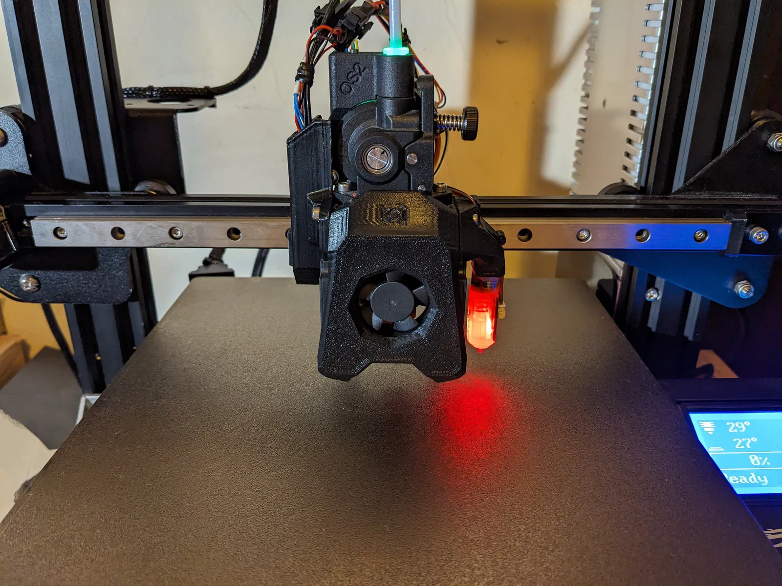
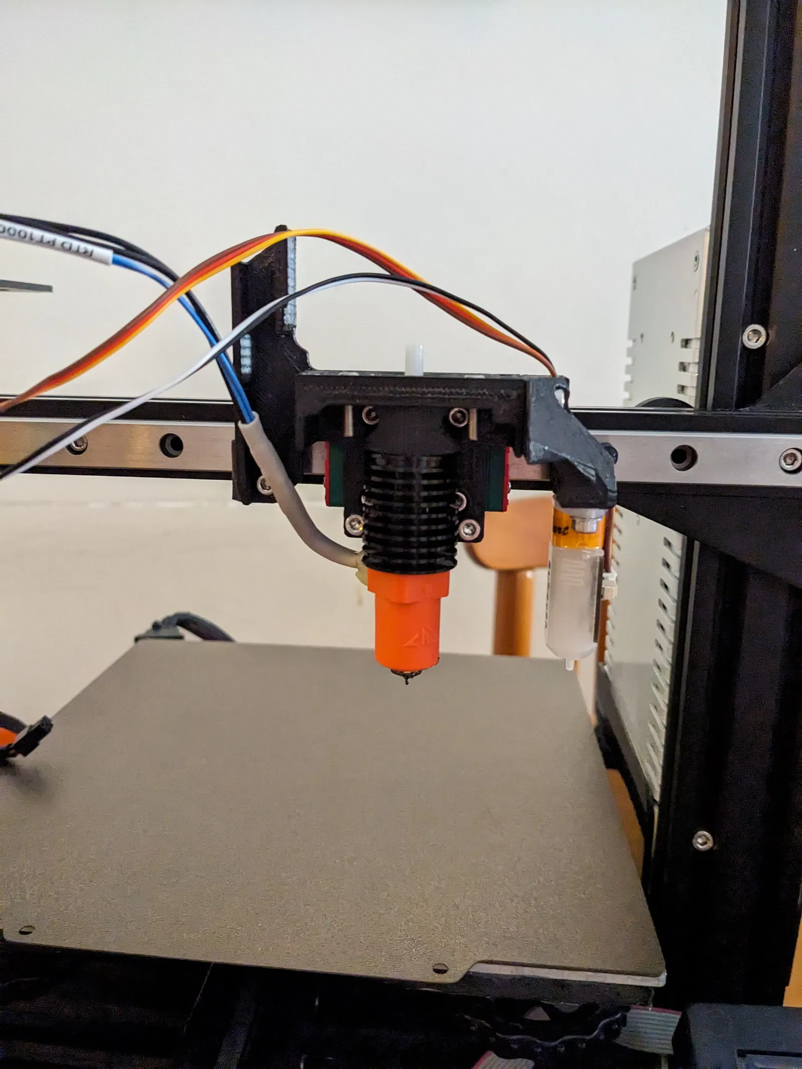
-- Ghé thăm /3d-model/nang-cap-toc-do-cho-may-in-3d-ender-3 -- 15/10/2023: Thêm ngàm cho Đầu dò cảm biến bề mặt đáy Eddy Current Beacon, được thiết kế bởi Sixpack99. Đầu dò được gắn bằng cách sử dụng bộ phận “X Belt Lock” đã được sửa đổi, có hai lỗ (2) 4.2 mm để lắp các ốc lục giác nhiệt M3 L6. Đầu dò Beacon gắn vào bộ phận in “Beacon Adapter” bằng hai (2) bu lông chìm M3 L8. Cuối cùng, hai bộ phận được bù trừ theo chiều dọc bằng hai (2) ốc đệm M3 L20. A simple remix to the original Apogee toolhead design, to accommodate a V6DM + a CHC Pro, in lieu of a Rapido HF hotend. The hotend setup used is mostly equivalent to a Rapido HF hotend, but at half the Rapido's retail price (~50€ instead of the usual 100€ for a Rapido HF). It does away with the stock POM wheels and the stock X axis aluminum bracket/carriage and instead uses a 300 mm MGN12H linear rail. The whole hotend assembly bolts directly on the MGN12H carriage block. The hotend heatsink is cooled by a single 3010 24 V dual ball bearing fan, while a pair of 24 V 12k RPM 4010 fans provide ample cooling capacity for most day-to-day print jobs. (Optional) An EBB36 CANbus board can also be mounted on the back of the Orbiter's pancake stepper motor. The total cost for this upgrade (including all the optional add-ons) comes out to roughly 200€. The drawbacks of this configuration are namely: * The loss of ~25-30 mm of Z-axis travel. This is unavoidable as it's a direct drive (DD) setup.
- The loss of ~10-15 mm of X axis travel (this only applies if you are using an EBB36 board) Note: The EBB board has to be mounted really close to the back of the extruder (~1 mm away from the back of the stepper motor). This, unfortunately, is unavoidable due to the very low clearance with the printer's frame at either end of the X axis. This is the cause for the loss of some X axis travel + being unable to use a mounting solution for the EBB board such as this one: https://github.com/KayosMaker/CANboard_Mounts/tree/main. The lack of proper strain relief for my CANbus harness on the EBB36 end might prove an issue later on. A suitable, ready-made over molded cable might be the solution to this issue. Use PETG/ABS/ASA for all the printed parts. Bill of Materials (BOM): As far as mounting hardware goes, you'll need: 11 x M3 thin square nuts (1.8mm max thickness) - get the M3 20 or 50 pcs option from here: https://www.aliexpress.com/item/1005001612157787.html
- 4 x M2.5 L15 Hex Bolts for mounting the V6DM to the Hotend Base (https://www.aliexpress.com/item/1005003521117223.html)
- 2 x M3 L30 Hex Bolts for securing the Belt Lock to the Hotend Base
- Approximately 20 x M3 L8 Bolts (12 of them will be used to mount the linear rail to the X axis 2020 aluminum extrusion - subtract 1 if you are using an EBB36 as the Rail Stop EBB36 occupies one hole where a bolt would normally go).
- Ten (10) (or so) M3 L10 Bolts
- 12 x M3 T-nuts/hammer nuts (11 if you're using an EBB36)
- A short length of PTFE tube (~ 10 cm is more than enough) The BOM mostly remains the same as the original Apogee (which can be found here) but having a small assortment or a kit of various lengths of M3 bolts in hand while assembling is good advice. You can such a kit for approximately 6-8€ on Aliexpress. Even if you don't use it while making this, it's honestly really useful to have the exact bolt you need lying around when you are designing or making something in the future. Toolhead Parts (Total Cost: ~110€): * 1 x 300 mm MGN12H Stainless Steel Linear Rail: https://www.aliexpress.com/item/1005004535281832.html
- 1 x V6DM Heatsink: https://www.aliexpress.com/item/1005005195556343.html
- 1 x V6 Style Bi-Metal Heatbreak (threaded version): https://www.aliexpress.com/item/1005001927523189.html
- 1 x CHC Pro Hotend - PT1000 Version: https://www.aliexpress.com/item/1005003936528202.html
- 1 x 0.4 or 0.6 mm CHT Volcano Nozzle (Clone): https://www.aliexpress.com/item/1005005503701946.html
- 1 x 3010 24 V Dual Ball Bearing Fan (WINSINN) https://www.aliexpress.com/item/1005003883192641.html
- 2 x 4010 12k RPM 24 V Dual Ball Bearing Fans (GDSTime) https://www.aliexpress.com/item/32799376487.html (I'd highly recommend going with the 12 k RPM version of these fans, if trading a bit more noise for more airflow isn't an issue for you).
- 1 x BL Touch/BL Touch Clone (I'd recommend a 3D Touch from TriangleLabs if you want to go with a clone) - approx. 15€ You'll also need a new timing belt for the X axis, I used this one: https://www.aliexpress.com/item/902692789.html (6 mm wide - 1 meter long) These are POWGE branded belts, overall really good quality with 5 pairs of fiberglass cores. You can also go with GATES branded belts but they're basically more or less the same thing and they're also a bit pricier. One meter is more than enough for the job. Cut the belt roughly to size, then cut to the exact length whilst assembling the tool head. Leaving some extra length is always a good idea as if you cut it short it'll be hard to grip the belt in order to to press it into place in the belt locking part that sits underneath the X axis extrusion. Extruder (Total Cost: ~ 70€): Orbiter v2.0 Extruder: https://www.aliexpress.com/item/1005003667391015.html
- Orbiter Filament Sensor v2.2 (Optional): https://www.aliexpress.com/item/1005004284790893.html Optional Add-Ons (EBB36/CANbus): The EBB36 board itself can be bought from here. Don't purchase the more expensive version with the MAX31865 amp, as we won't be needing it. If you opt not to install an EBB36 to your printer, please note that if you have a mainboard like with 4 stepper motor drivers, you won't be able to implement G34/Z_TILT_ADJUST to your printer. This is because the EBB36 frees up a driver chip on your mainboard (which was previously used to drive the extruder motor), allowing us to use the newly freed chip to independently control both of the Z-axis steppers. More information about all the other necessary electronics to setup CANbus on your printer can be found here: [TBA] CANbus Wiring Harness (Total Cost: ~10€): You can make your own wiring harness using 4 x 20 AWG wire and crimp on the necessary Molex connectors. I used this cable, which comes pre-crimped with a Molex connector on one side - you can get away with crimping Molex connectors if you choose to connect the other end of the cable to the screw terminals of the U2C v2.1 board, if you're using one: https://www.aliexpress.com/item/1005004663434820.html I then braided it and slid a 6 mm PET sleeve over it (https://www.aliexpress.com/item/1005002734938651.html) along with some heat shrink to make it look pretty. An alternative to the DIY version would be a ready made cable by Molex, availiable through Digikey: https://www.digikey.gr/en/product-highlight/m/molex/micro-fit-overmolded-cable-assemblies (not tested) Rough Assembly Instructions: * Disassemble your old toolhead completely - remove the stock aluminum carriage/POM wheel assembly completely from the printer, as well as the old X axis belt.
- Insert the M3 thin square nuts onto the respective slots found on most of the parts you have printed.
- Install the Hotend Base printed part onto the MGN12H carriage block using 4 x M3 L8 bolts.
- Install the Belt Lock printed part to the Hotend Base using 2 x M3 L30 bolts.
- Assemble the hotend: Screw the nozzle in the CHC Pro hotend fully, then back it out a turn or so so that there is a 0.5 - 1.0 mm gap between the nozzle and the hotend. Screw the heatbreak in the hotend - make sure it is sitting flush with the nozzle. Failure to do so will result in a blob of plastic leaking out of your hotend i.e. you'll have a bad day. Screw the hotend/heatbreak assembly to the V6DM heatsink. Verify that the nozzle/heatbreak hasn't come loose.
- Install the hotend to the Hotend Base printed part by screwing 4 x M2.5 L15 bolts to the V6DM heatsink through the four bolt holes found on top of the printed part. Mind the routing of the heater/thermistor cables while doing this.
- Slide all 3 fans into place in the Fan Shroud Printed Part.
- Install the linear rail with the partially assembled toolhead onto the printer. Use M3 L8 bolts + a T-nut for each bolt. Use all the bolts holes in the linear rail. Make sure all the nuts rotate 90 degrees when fully tightened.
- Finish assembling the toolhead by installing the Fan Shroud to the Hotend Base, as well as securing the Wire Cover printed part with a M3 L10 bolt to the Hotend Base. Insert the PTFE tube to the V6DM heatsink before instalingl the Orbiter extruder on the toolhead. Don't forget the BL Touch + its mounting arm if you're using one. After that, all you have to do is run through the usual calibration steps (rotation distance, PID tuning, input shaper, as well as changing the kinematics settings on your printer.cfg file). My instructions definitely do not cover all the nitty gritty details, however they should give you a pretty good idea of the steps required to perform this upgrade from start to finish. Configuring the U2C v2.1/EBB36 - Setting up CANbus: This video explains the whole process quite clearly - it was honestly not as difficult as I originally anticipated: P.S.: I've also found this video to be extremely helpful for setting up my kinematics settings (X, Y min/max, etc) in Klipper:
Giấy phép
Tác phẩm này được cấp phép theo
Creative Commons — Attribution — Noncommercial — Share AlikeCC-BY-NC-SA

File mô hình


Chưa có bản in nào được khoe. Hãy là người đầu tiên!

Chưa có bình luận nào. Hãy là người đầu tiên!