



Thùng rác in Vase Mode
 BybobmakesLikes2.5KDownloads17.5K
Build another version of this model.
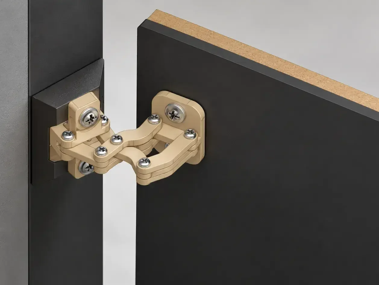
ClearSwing 90 – Concealed Multi-Link Hinge
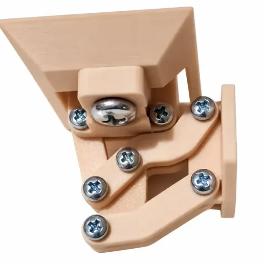
ClearSwing 90 is a compact, 3D-printable concealed hinge designed to open a door up to 90° while keeping the mechanism hidden behind the panel.
The multi-link mechanism controls the door's movement, helping it clear nearby walls and obstacles during opening.
Enjoyed this model? It means a lot to me that something I designed for my own home might now be useful in yours. If you'd like to say thanks, subscribe to ClearSwing 3D on YouTube. If you enjoyed the video too, I'd appreciate a like. Thanks for printing my designs!
Features
90° opening angle
Seven pivot points and a six-link mechanism
Compact concealed design
Designed for 3D printing
Suitable for custom cabinets, enclosures, and DIY projects
Required Hardware and Tools
Hardware:
M3 × 10 mm Phillips head screws
M5 × 12 mm Phillips head screws
Tools:
M3 tap No. 1 (first-cut tap)
M5 tap No. 1 (first-cut tap)
3 mm drill bit
Phillips screwdriver
Hole Preparation and Thread Cutting
After printing, some holes may require finishing to ensure proper assembly and smooth movement.
1. Threaded mounting holes
Use the M3 and M5 taps to cut internal threads in the designated screw-fastening holes.
For standard right-hand threads, turn the tap clockwise to cut the thread in the same direction used to tighten the screws.
Keep the tap aligned with the hole and work slowly to avoid damaging the printed plastic. Reverse it periodically to clear debris. A finishing tap may be needed to complete the threads.
2. Through-hole calibration
Use the 3 mm drill bit to carefully calibrate the non-threaded M3 through-holes, removing any printing irregularities and ensuring the screws pass through smoothly.
Do not use the 3 mm drill bit to enlarge holes intended for M3 thread cutting.
3. Pivot joints
Make sure the moving links rotate freely around their pivot points. Avoid overtightening screws that act as pivot shafts.
Assembly
Print all hinge components.
Clean the parts and remove any printing defects.
Cut the required M3 and M5 internal threads in the screw-fastening holes.
Calibrate the appropriate through-holes with the 3 mm drill bit.
Assemble the linkage using M3 × 10 mm and M5 × 12 mm screws.
Check that all moving parts rotate freely.
Test the full 90° opening movement before installation.
Important Notes
Verify all clearances before installing the hinge.
Do not force screws into incorrectly sized holes.
Avoid excessive tightening, as this may restrict movement or damage the plastic.
This is an experimental mechanical design. Test the hinge before using it on heavy doors.
BybobmakesLikes2.5KDownloads17.5K

 BymakerxLikes0Downloads359

 By178222178222_2484344Likes449Downloads1.7K

 Byquibeck_3353173Likes1.5KDownloads11.5K

 ByVaclav_ZahradkaLikes181Downloads1.2K

 ByowlartLikes527Downloads1.3K

 Bytjfenwick_306961Likes385Downloads1K

 ByAWSWLikes148Downloads585

 ByfifindrLikes216Downloads611

 Bymatus158Likes0Downloads114

 Bym-collectableLikes0Downloads3.9K

 Byskloter_271869Likes147Downloads429