


New
Build another version of this model.
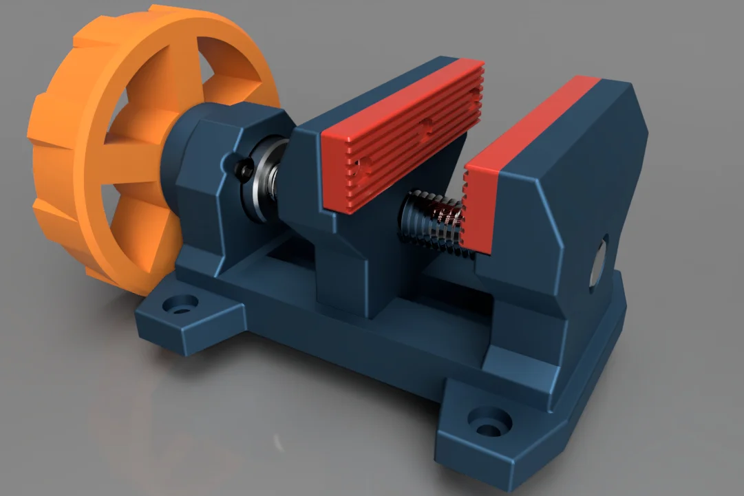
There are many great designs for hobby and craft vises that utilize 3D-printed parts. I use several of these very effectively for soldering, gluing, painting and other hobby oriented tasks.
HOWEVER...
I also have a need for something heavier, for the garage, to perform tasks beyond hobby and craft duty. I needed a small, but capable vise strong enough to hold items when sawing, grinding, and torch soldering.
My design for this Bench Vise utilizes common hardware that provides MUCH greater strength than any 3-D printed part can provide, yet is readily available. I chose a 5/8-11 x 6"L bolt for the lead screw as it provides enough travel per revolution to work effectively and is readily available in comparison to ACME threaded options.
I printed the main body and floating jaw in PETG-CF with 5 walls and 22% gyroid infill. The handle was printed with PETG-GF filament with the 3 walls and 22% gyroid infill. I printed the jaw pads with Rapid TPU-95A with 3 walls and 22% infill.
Hardware Required:
Item
Qty
Description
Part Number
Purpose
1
1
5/8"-11 UNC x 6"L Hex Bolt - Full Thread
Everbilt 801166
Lead Screw
2
1
5/8" x 1-1/8" x 1/2" Shaft Collar
Hillman 838621
Retainer
3
1
5/8"-11 UNC Hex Nut
Everbilt 801786
Drive Nut
4
2
5/8" x 1" x #14 gauge Machine Bushing
Hillman 882393
Thrust Washer
5
6
#4 x 1/2" Black SS sheet metal screw
(Amazon) X004P0P57P
Retain Jaw Pad
Refer to animation for assembly sequence. Note the Shaft Collar is tightened with the hex set screw after aligning with the slot in the main base.
Assembly:
Affix jaw pads to vise jaws.

Insert hex bolt into handle and seat head into hex recess.

Place one machine bushing on bolt.

Pass bolt through vise body and slide remaining machine bushing and collar onto bolt.

Press nut into hex recess in floating jaw and thread bolt through jaw until flush with outer body Optional: Depending on your print tolerances, you may add a drop of CA adhesive to help retain the nut during jaw retraction.

Align collar setscrew with recessed slot in vise body and tighten appropriately. Optional: You may wish to file a flat on the bolt threads and/or drill a shallow divot for more positive engagement.


Press Handle Center Cap into recess.

Counterbore mounting holes are sized for #10 pan head screws.
Optional: Portable Bench Clamp (no-drill option for mounting)


Hardware Required for Bench Clamp:
Item
Qty
Description
Part Number
Purpose
1
1
3/8"-16 UNC x 3-1/2"L Hex Bolt - Full Thread
Knob
2
2
3/8"-16 UNC Hex Nut
Knob
3
1
3/8"-16 UNC Hex Thin Jam Nut
Lock Nut
4
4
#10-32 x 5/8"L Machine Screw
Vice Mounting
5
4
#10-32 Hex Nut
Vice Mounting


 Bydelloo2008Likes0Downloads242

 Bykjus_448782Likes314Downloads677

 ByelitailLikes0Downloads131

 Bythorin-oakenshieldLikes0Downloads531

 Bychubbs8697_2027893Likes585Downloads1.7K

 ByleonicLikes0Downloads1.4K

 ByfifindrLikes500Downloads4K

 ByVC_DesignLikes679Downloads3.6K

 ByDan Schwartz SchwartzLikes744Downloads3.4K

 Byquibeck_3353173Likes965Downloads1.9K

 Bydenis-3dLikes0Downloads265