



New
Portal Turret - Mk. II
 ByjoranLikes0Downloads213
Build another version of this model.
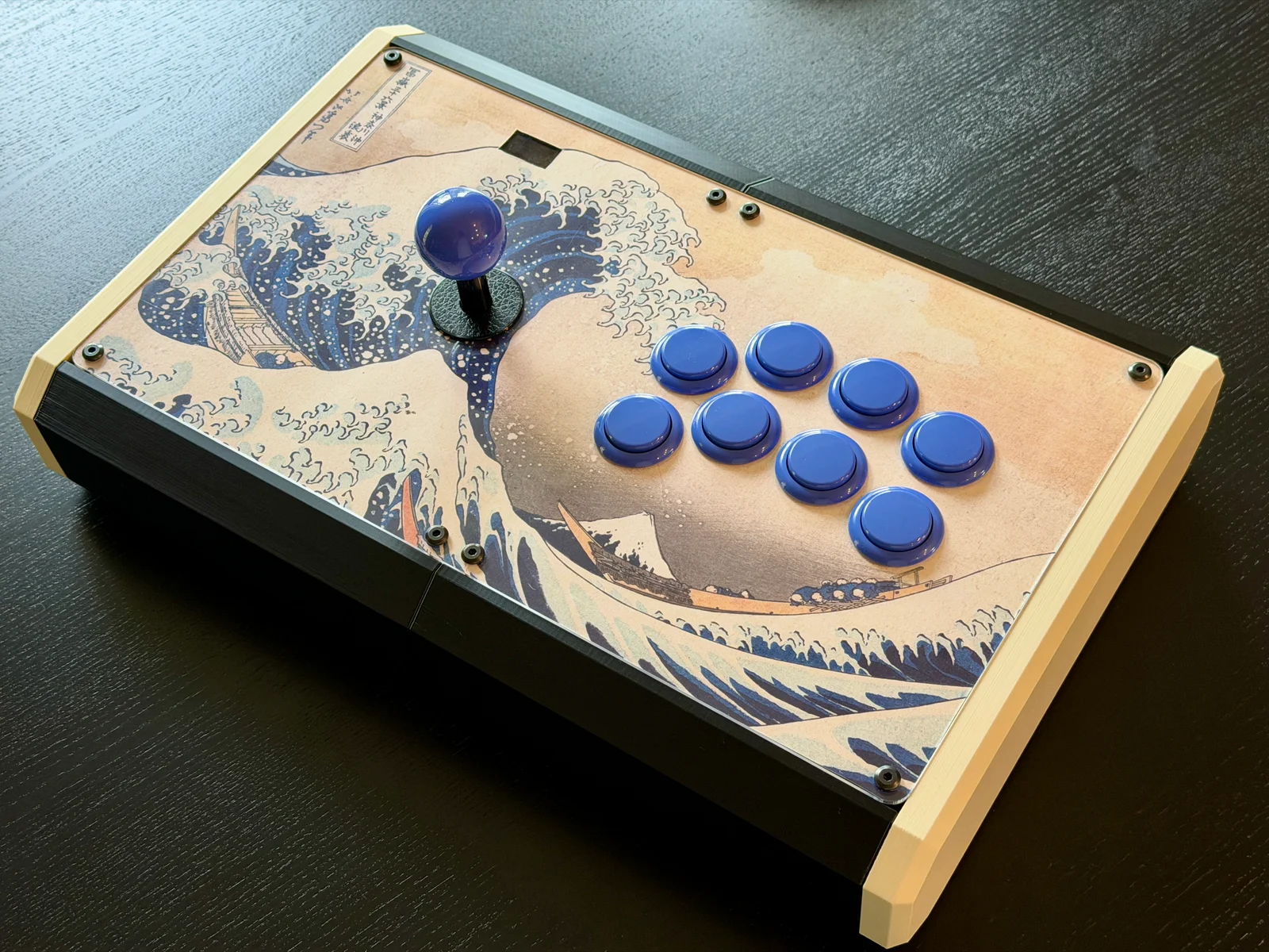
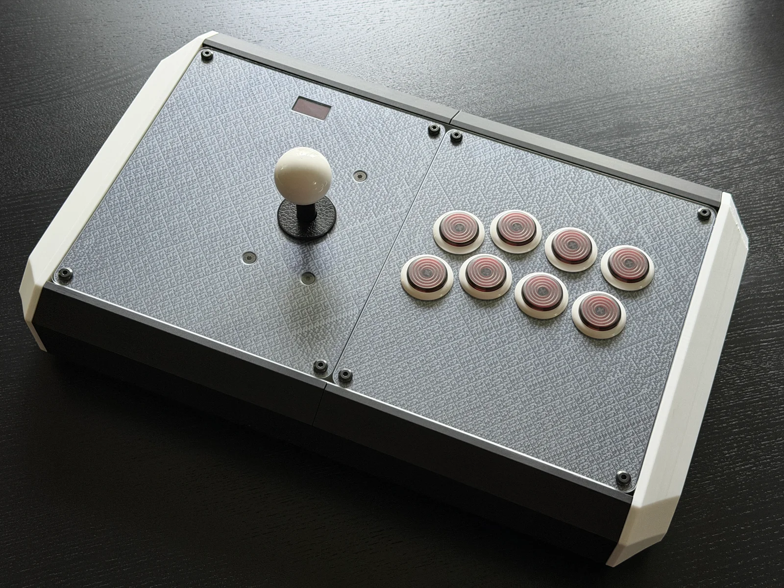
Welcome to PANTHERv2! For the Mad Cat in us all! I really like how this came out, and my future designs will probably have these hidden joining features too.
As always, I'm open to any/all suggestions – feel free to drop them in the comments!
RAF
0.2 - Current version
CHAMv3 Panels - PANTHER uses these panels
Any provided OnShape links are to my working documents, are the most updated version of the project, and may differ from the files uploaded here.
Will add the guitar strap ENDCAP -- if there is a interest.
May add a center brace -- if I come up with something.
Null

PANTHERv2. This is an updated version of my MadCatz TE1 inspired enclosure. The main changes are an alternative TES style endcap, slightly thicker bezel, and the hidden M6 bolts. There are also some small changes to the endcaps to help alleviate the "hull line". This updated version is still just as sturdy as the first!
PANEL COMPATIBILITY. PANTHERv2 is compatible with all CHAMv3 panels.
Please clickHERE for the CHAMv3 Button Panels Printables page!
WARNING: The completed build takes ~1kg of filament! Ensure your printer & slicer are well-tuned before attempting this project!
All PANTHER Parts:
4 Walls / 20-30% Cubic Infill / No Supports
Tested in PLA and PETG
ENDCAPs may need to be oriented diagonally in your slicer.
The corners of each part may lift from the build plate – ensure strong adhesion!
The JOINT should be oriented upright
BUTTON PANELS (located HERE):
4 Walls / 20-30% Cubic Infill / No Supports
PLA preferred over PETG for rigidity (and prettier colors)
The exterior face of the panels should face the build plate.
WARNING: Do not use M6 bolts longer than 35mm! It will puncture the case!
Part
Quantity
Notes
M6x35mm Countersunk Bolts
4
For center JOINT. I use THIS set from Amazon
M6x25mm Countersunk Bolts
4
For ENDCAPs.
M6 Nuts
8
Square preferred, but Hex also works
24
Can use the 6x4x4 ones too
24
For top panels and joint
(Optional) M4x16 Countersunk Bolts
8
For bottom panels, but you can use furniture bolts
6
for Neutrik and PCB mounts
M3x6 Bolts
6
See above
Arcade Stick PCB
1
RP2040 Advanced Breakout Board or Brook
1
Or hand-wire
Arcade Stick Buttons and/or Joystick
n/a
Sanwa JLF + OBSF-30 if unsure
1
or similar D-Mount alternative
Soldering Iron
1
For installing HSIs
PRINT ALL PARTS
- You will require x2 ENDCAPs, and x1 of each other part.

INSTALL BODY HEAT SET INSERTS (HSIs)
- HSIs are installed via soldering iron – this requires a steady hand. Install HSIs as straight as possible into the hole.
- Recommend watching some YouTube videos on HSI installation if this is your first time. I like to slowly insert until the final 1-2mm, then I use a flat metal object to push it flush with the hole and allow it to cool.
- The body requires x16 M4 HSIs in total.
- Each FRONT and BACK requires x4 M4 HSIs that align with the bolt holes in the upper and lower panels.

- The JOINTs require x8 M4 HSIs in total.
- Each JOINT requires x4 M4 HSIs that align the with the countersunk holes in the rails of the FRONT and BACK parts. They help secure the JOINT to the body in addition to the M6 bolts.
- DO NOT INSTALL HSIs INTO THE HEX HOLES OF THE JOINT!
INSTALL M3 HSIs
- x2 M3 HSIs install into the Neutrik mount in the center of the 2 BACK pieces.
- Due to the its location, it is not possible to use M3 nuts/bolts to secure the neutrik.
- x4 M3 HSIs install into a PCB mount on the upper or lower panels.
- There are several options—use the mount that works best for your layout.
- Honestly, I don't install these. I snip a bit of toothpick flush to the top of the mount and use a self-tapping screw.
ASSEMBLE BODY
- Line up the two FRONT pieces, insert x2 M6 nuts into the slots, and align it with the hole.
- Place the correct JOINT piece over it, and use x2 M6x35mm bolts to join the pieces together.
- Fasten 4 M4x16mm furniture bolts through the BODY into the JOINT.
- Repeat with the BACK pieces.


JOIN BODY WITH ENDCAPS
- Insert x2 M6 Nuts into the slot in the ENDCAP and align with the hole.
- (optional) Place SHIM to increase the width of the case to counteract filament shrinkage.
- Align one of the halves of the BODY and use an M6x25 bolt to join the pieces.
- Repeat with the other side, then with the other ENDCAP.
- Ensure everything is square, and all bolts are fully tightened.


INSTALL PANELS AND CONTROLLER HARDWARE
- If you made it this far, then it's the home stretch!
- Install your controller hardware and wire everything up.
- Ensure all panel bolts are fully tightened and you're good to go!
- NOTE: If you find the panels are fitting a bit too tight, loosen the screws for the end caps, pull the frame outward, and retighten the endcaps.

PLAY VIDEO GAMES
Happy Printing! If you would like to support my work, please visit my Ko-fi!
RAF
ByjoranLikes0Downloads213

 Bybob-wulffLikes0Downloads201

 ByvladtheinhalerLikes64Downloads256

 ByUpcrid3D_1585693Likes48Downloads212

 By3Deanprinting_643609Likes0Downloads7


 ByatrushingLikes0Downloads300

 Byvitals78_1747561Likes43Downloads74

 ByckthLikes148Downloads2.4K

 ByJac2307_889487Likes36Downloads256

 BynasikLikes0Downloads274

 ByshionnLikes0Downloads144