



Còi Tàu Hơi Nước Mini
 ByfifindrLikes500Downloads4K
Build another version of this model.
Tired of fighting with the stock xTool M2 hold-down feet every time you need to remove and reposition a project?
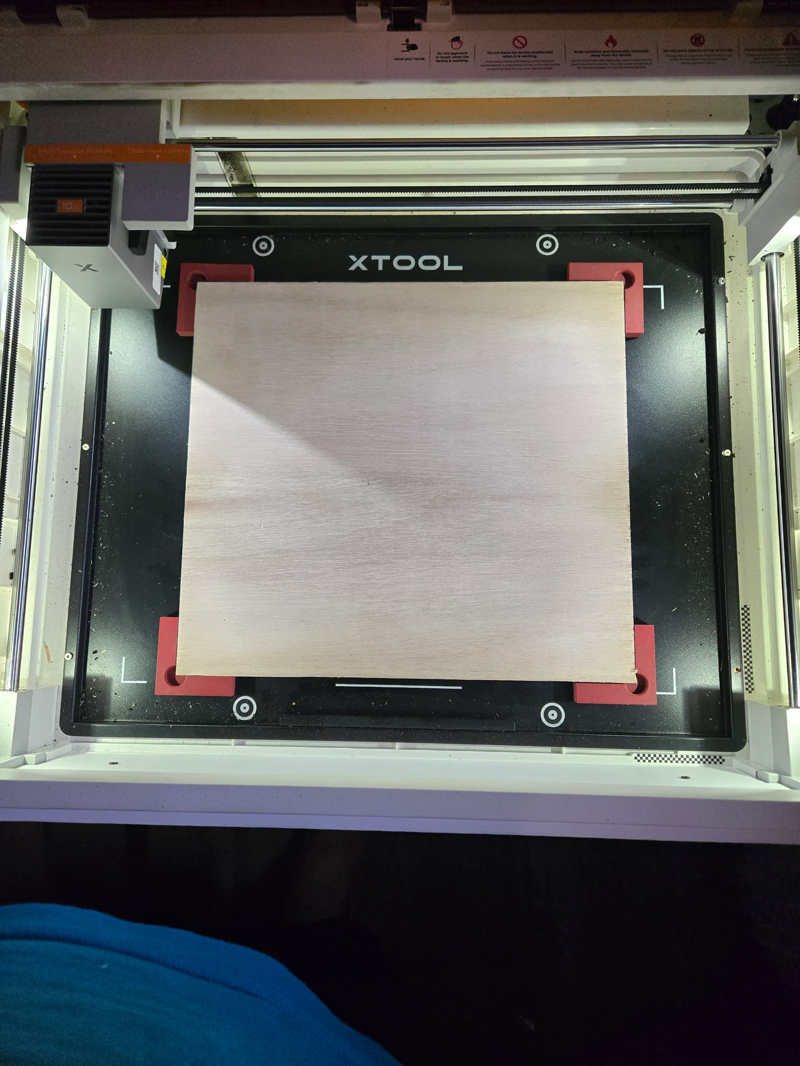
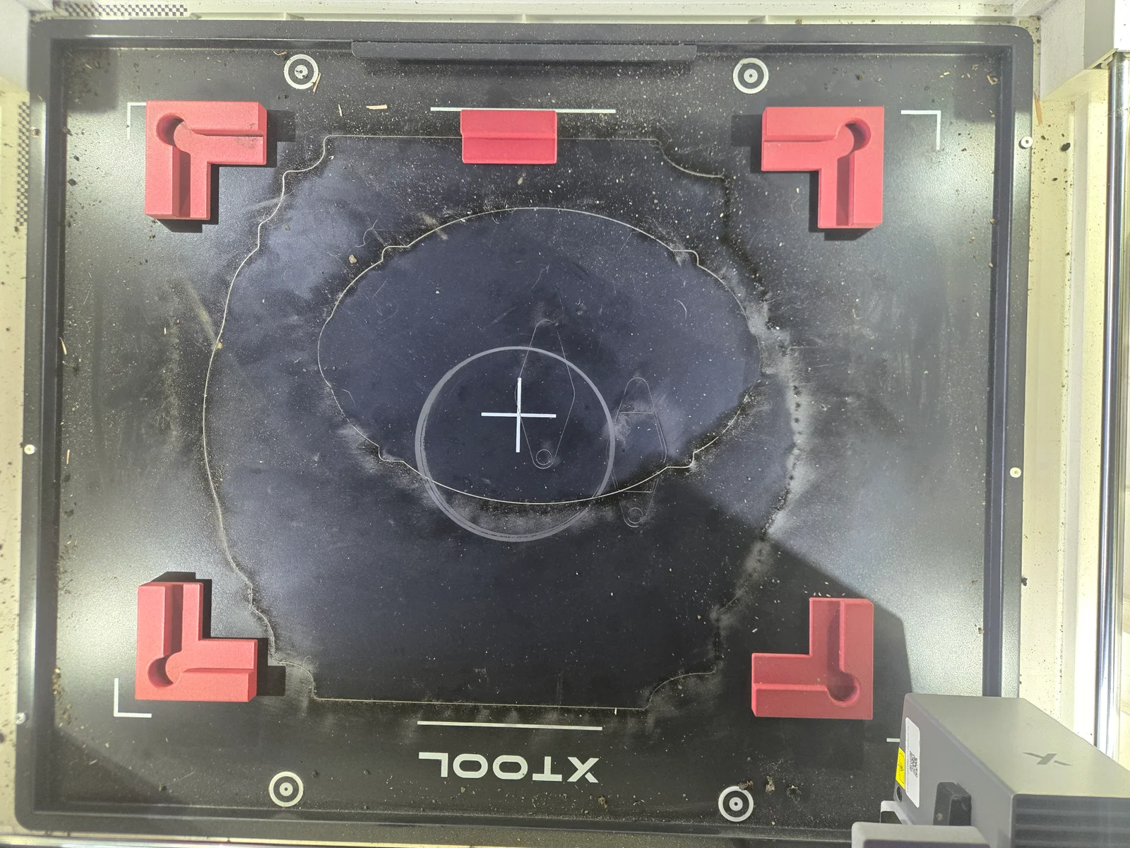
This magnetic alignment jig was designed to provide fast, repeatable material registration for the xTool M2 laser cutter. Simply place your material against the locating faces, remove it when needed, and drop it back into the exact same position later.
The jig uses magnetic corner fixtures that reference the edges of the material rather than the corner itself. A built-in corner relief allows chipped, rounded, or imperfect plywood corners to seat properly against the locating surfaces without affecting alignment.
Two versions are included to accommodate the most common material thicknesses:
3 mm (1/8") Version – Designed for 3 mm / 1/8" material. The retaining walls are low enough to allow edge-to-edge engraving and printing without the print head contacting the jig.
6 mm (1/4") Version – Designed for 6 mm / 1/4" material, providing additional support for thicker stock.
Choose the version that best matches your material thickness and workflow.
This makes the jig ideal for projects requiring multiple operations such as paint filling, resin filling, sanding, staining, printing, or multi-pass engraving.
Why I Made This
I originally designed this because I got tired of fighting with the stock xTool M2 hold-down feet.
The factory hold-down feet work well for preventing material movement, but they don't provide repeatable registration. If you remove a project for painting, resin filling, sanding, inspection, or printing, you often spend unnecessary time trying to line everything back up.
This jig solves that problem.
Place your material against the locating faces, remove it whenever needed, and return it to the exact same position every time.
Features
Magnetic mounting system
Repeatable material registration
Edge-referenced positioning
Built-in corner relief for damaged or imperfect corners
Embedded magnet pockets
Two wall-height options:
3 mm (1/8")
6 mm (1/4")
Fully parametric Onshape model for customization
Compatible with virtually any laser engraver that has a steel work surface
Choosing the Correct Jig
Recommended for:
3 mm or 1/8" plywood
Edge-to-edge engraving
Edge-to-edge printing
Applications where the print head must clear the jig
Recommended for:
6 mm or 1/4" plywood
General engraving
Cutting thicker material
Applications where additional material support is preferred
Embedded Magnet Installation
The magnet pockets are designed to capture the magnets during printing.
Add a pause in your slicer immediately before the magnet cavities are sealed.
When the printer pauses:
Insert the magnets.
Verify the polarity is correct.
Resume printing.
The remaining layers permanently capture the magnets inside the part.
No glue required.
Included Files
Corner Fixture STL files
Side Retaining Strip STL files
3 mm (1/8") Jig
6 mm (1/4") Jig
Print-ready STL files
Fully parametric Onshape source model
Onshape Source
Want to customize it?
The complete parametric model is available here:
The design was created as a fully parametric Onshape model, allowing dimensions such as material size, wall thickness, wall height, magnet size, and corner relief to be easily customized for your own workflow.
You can easily modify:
Material size
Wall thickness
Wall height
Magnet diameter
Magnet depth
Corner relief dimensions
Custom workholding applications
Recommended Print Settings
Layer Height: 0.20 mm
Walls: 3–4
Infill: 20% or greater
Supports: Not Required
Material: PLA, PLA+, PETG, ASA, or similar
Hardware Required
Three 10 × 2 mm neodymium magnets per corner fixture
Two 10 × 2 mm neodymium magnets per retaining strip
(Magnet sizes can be changed in the Onshape model if desired.)
Perfect For
Sign making
Multi-pass engraving
Paint-filled engravings
Resin-filled engravings
Edge-to-edge printing
Edge-to-edge engraving
Material registration
Repositioning workpieces
Laser engraving workflows
Laser cutting workflows
ByfifindrLikes500Downloads4K

 ByVC_DesignLikes679Downloads3.6K

 ByDan Schwartz SchwartzLikes744Downloads3.4K

 Bychubbs8697_2027893Likes585Downloads1.7K

 Byquibeck_3353173Likes965Downloads1.9K

 ByRungeKuttaLikes229Downloads1.2K

 ByEadubsLikes228Downloads1.3K

 ByJeremyVillalo_760366Likes68Downloads767

 ByZED4EverLikes313Downloads5.2K

 Bykjus_448782Likes314Downloads673

 BySchmitzBertLikes95Downloads629

 ByNathanKun_342409Likes132Downloads590