



Khuôn Vẽ Sơ Đồ Mạch Điện Tử (Kích Thước Thẻ ATM)
 ByBoonby_1059917Likes659Downloads1.2K
Build another version of this model.
Section One: Preparing the Cams and Drive Shaft
This phase involves setting up the main horizontal drive mechanism that will convert the rotational motion of the crank into vertical movement.
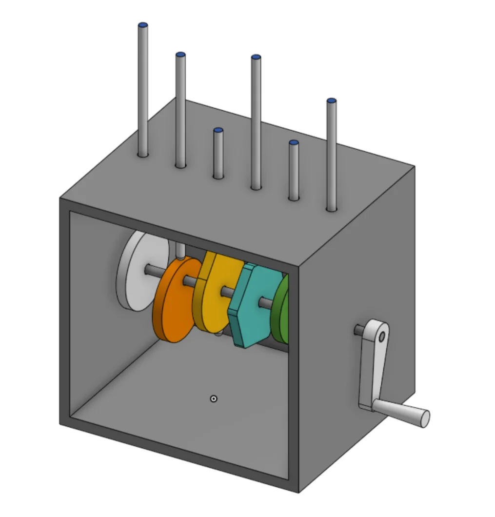
To begin, identify your main horizontal drive shaft, which is the longest metal or plastic rod in your kit. Next, gather your five distinct mechanical cams, which include the round grey disc, the orange off-center circle, the yellow pear-shaped cam, the teal hexagonal cam, and the green snail-shaped cam. Slide these colored shapes onto the long horizontal rod one by one in the exact sequence shown in the final reference image. Take extra care to space them out evenly along the middle section of the rod so that each cam aligns directly beneath one of the five guide holes pre-drilled into the top roof of the main box housing.
Section Two: Main Box Housing and Drive Assembly
This phase integrates the prepared drive shaft into the structural frame of the box and attaches the manual interface.
Take your completed horizontal shaft assembly with the attached cams and carefully maneuver it inside the open cavity of the large grey box housing. Guide one end of the long horizontal rod through the circular hole located on the left side panel of the box, and push the opposite end through the corresponding hole on the right side panel. Ensure the rod can rotate freely within these side pivot holes without binding. Once the shaft is securely bridging the gap between the two walls, take the small grey crank handle lever and affix it firmly to the protruding end of the horizontal rod on the outer right face of the box. Rotating this handle should now cause the entire internal shaft and all five attached cams to spin in unison.
Section Three: Vertical Follower Rod Installation
This final phase completes the mechanical link by adding the vertical rods that travel along the rotating profiles of your cams.
Locate your five vertical follower rods. Working from one side to the other, slide each vertical rod downward through the designated guide holes on the flat top roof of the box housing. Lower each rod completely into the box until its smooth bottom tip rests directly on the outer perimeter edge of its corresponding colored cam below. Ensure that each vertical rod moves smoothly up and down within its guide hole without tilting or catching.
ByBoonby_1059917Likes659Downloads1.2K

 ByFabianVeileLikes414Downloads1.5K


 ByactualnameLikes0Downloads385

 BynleinadLikes56Downloads188

 Byandrej-bLikes0Downloads180

 ByTheWallArtGuyLikes36Downloads115

 BygillisLikes121Downloads2.1K

 ByordinaryairLikes0Downloads142

 By3dfoundryLikes0Downloads117

 ByskimbeebleLikes0Downloads134

 ByiliamanLikes0Downloads183