



Đầu dò cảm biến lực tự chế giá $10 cho Ender 3
 ByBrokentooth_designsLikes17Downloads147
Remix of Giá đỡ đầu in E3D V6 cho máy in Ender 3 V2: Thiết kế tối ưu By Qris
Build another version of this model.
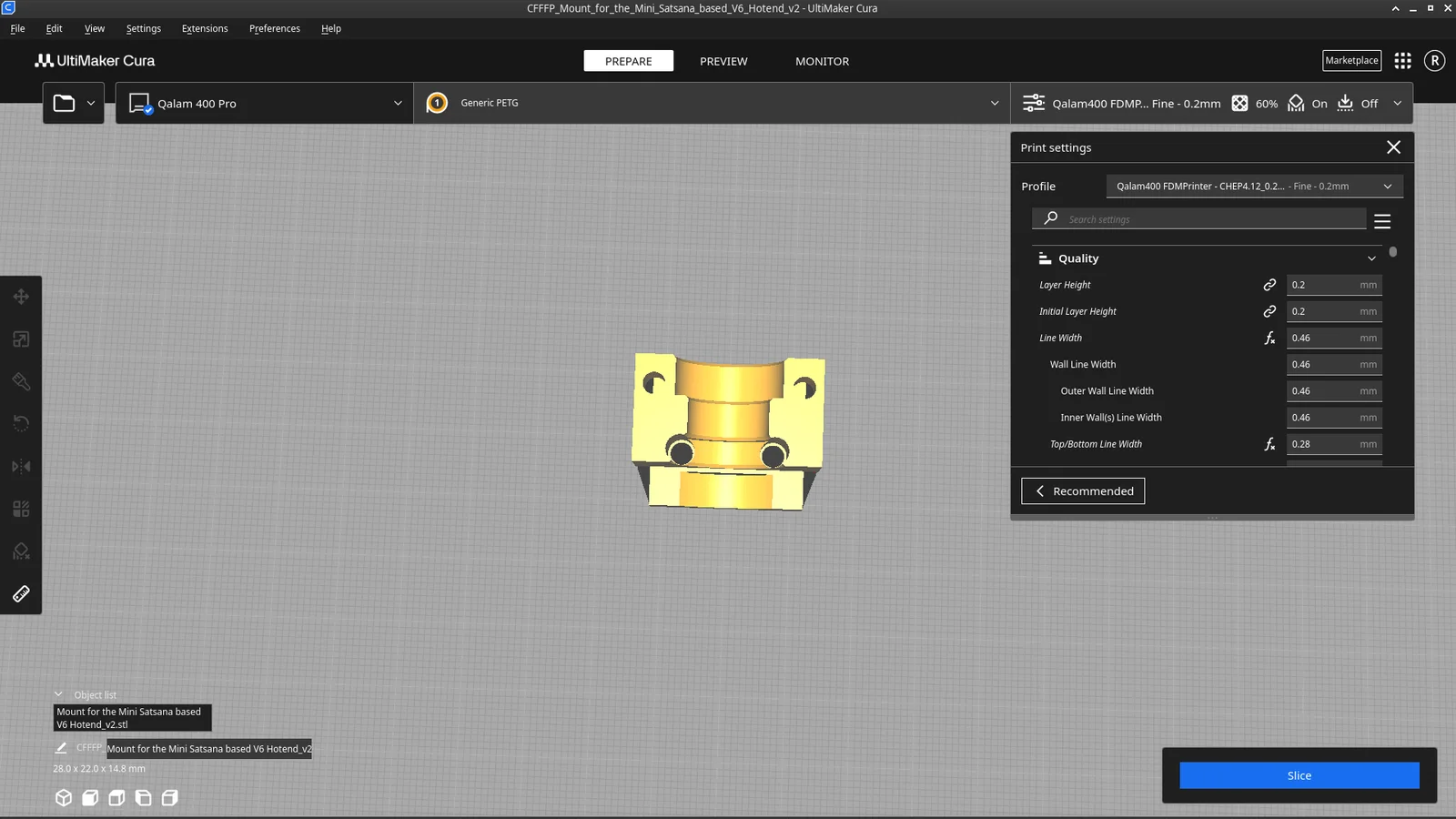
I created this mount while converting my modified Ender 3 V2 to use an E3D V6-style hotend with a compact Mini Satsana-based cooling setup.
The available Mini Satsana duct and V6 holder were suitable for the hotend, but they could not mount directly to my original Ender 3 v2 carriage in the arrangement I needed. I therefore combined the duct and hotend-holder geometry from the Printables design, created by @Qris you can check it out with this link, with the Ender 3 V2 carriage-adapter concept demonstrated in Victor Bared’s E3D V6 installation video. The original Printables model is described as a simple E3D V6 mounting and cooling solution for the Ender 3 V2, while the video demonstrates a compact adapter for installing an E3D V6 on the Ender 3 V2 carriage. (YouTube)
The resulting part provides:
Direct mounting to the original Ender 3/Ender 3 V2 X-carriage
Support for an E3D V6 or dimensionally compatible V6 clone
Mounting points for the Mini Satsana-based fan duct
M3 heat-set insert holes for repeatedly removing and reinstalling the duct
A compact, lightweight arrangement
Better serviceability than using screws directly in printed plastic
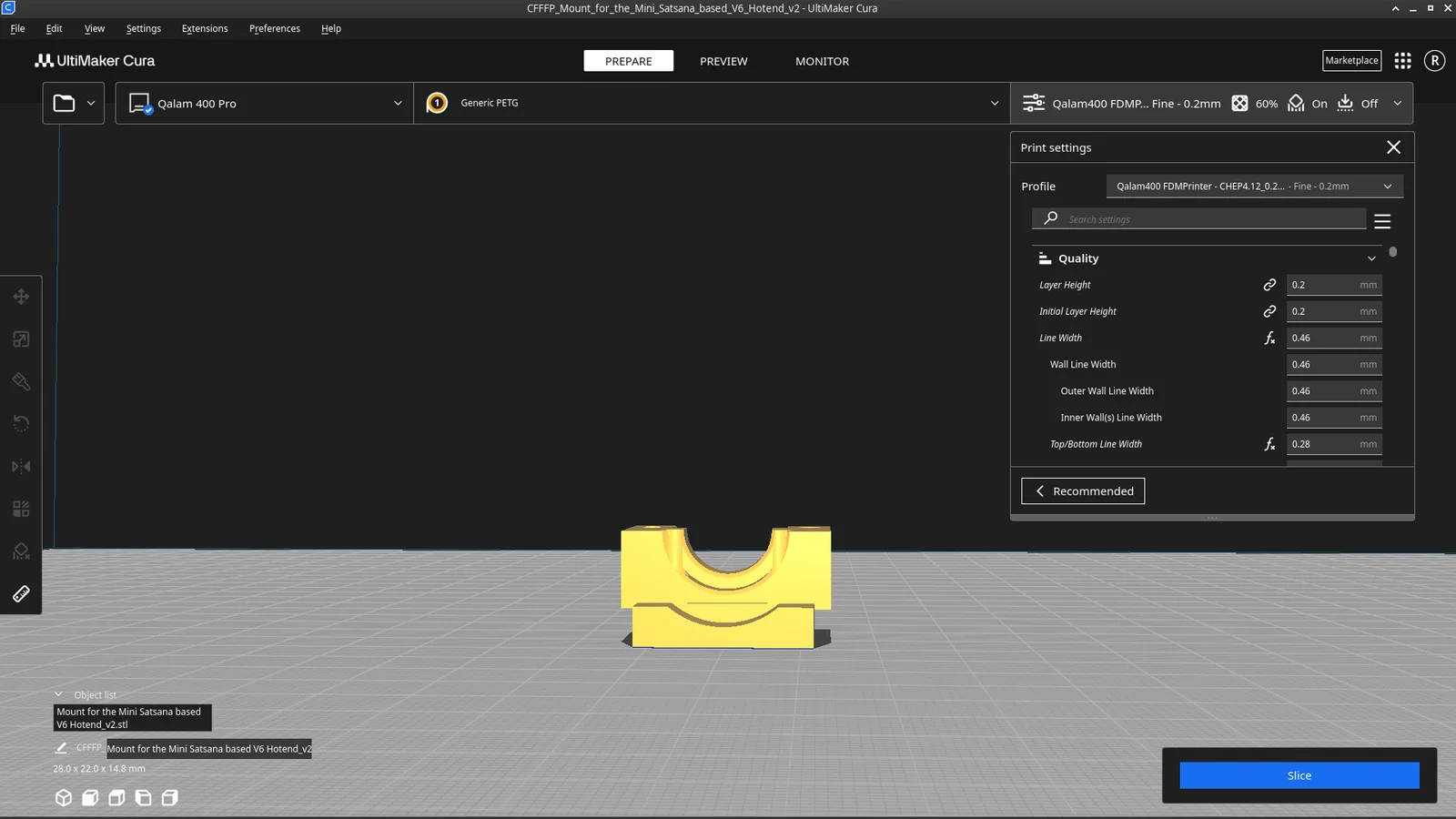
The lower mounting section was repositioned beneath the main hotend-holder body so that it interfaces correctly with the original carriage. The first prototype had this section on the wrong side. After reversing its position and test-printing the updated version, the carriage-hole alignment and physical fit were confirmed.
Design changes
The main changes made to the source components were:
Combined the Mini Satsana-compatible E3D V6 holder with an Ender 3 V2 carriage adapter.
Repositioned the carriage-mounting section underneath the hotend holder.
Preserved the original lower carriage-hole locations and diameters.
Added or modified the upper mounting holes for M3 heat-set inserts.
Adjusted the geometry so the cooling duct can be attached and removed without damaging the printed threads.
Kept the assembly compact to reduce unnecessary toolhead weight.
This is not merely the original mount with additional holes. The carriage interface and mounting orientation were modified to make the two designs work as one assembly.
Compatibility
Designed and physically tested around:
Creality Ender 3 V2 carriage
Standard Ender 3-style X-carriage mounting pattern
E3D V6-style hotend
Compatible E3D V6 clone hotends
Mini Satsana-based cooling duct
M3 heat-set inserts
Bowden extrusion configuration
It may also work with:
Ender 3
Ender 3 Pro
Other Creality machines using the same X-carriage mounting pattern
Compatibility with those additional machines has not yet been physically verified.
Before installation, confirm that your V6 clone follows standard E3D V6 dimensions. Clone heatsinks and grooves can vary slightly.
Required hardware
The exact screw lengths can vary depending on the duct, fan thickness and the type of heat-set inserts used.
Recommended hardware:
2 × original carriage-mounting screws
2 × M3 heat-set inserts for the upper duct mounting points
2 × M3 screws for attaching the Mini Satsana duct
E3D V6 groove-mount hotend
4010 hotend cooling fan
4010 x2 part-cooling blower and screws
Measure the required M3 screw length after installing the inserts. The screws should fully engage the inserts without reaching the bottom of the holes or contacting the hotend.
Heat-set insert information
The upper holes are intended for M3 heat-set inserts.
Before printing the complete part, measure the outside diameter and length of your inserts. M3 inserts are sold in several dimensions and do not all require the same printed hole.
For my version:
The upper mounting locations are for M3 inserts.
The lower carriage holes retain the original carriage-mounting dimensions.
The lower holes are not intended to receive M3 heat-set inserts unless your particular carriage arrangement specifically requires them.
Install the inserts slowly using a temperature-controlled soldering iron. Keep the insert perpendicular to the mounting face and stop once it is flush. Do not push it far enough to enter the hotend cavity.
Settings used for the prototype
These are the settings that are directly confirmed from the Cura configuration and the successful fit-test information available from the build:
Setting
Value
Material
Generic PETG
Nozzle diameter
0.4 mm
Layer height
0.20 mm
Initial layer height
0.20 mm
General line width
0.46 mm
Wall line width
0.46 mm
Outer-wall line width
0.46 mm
Inner-wall line width
0.46 mm
Top/bottom line width
0.28 mm
Printer profile visible during slicing
Qalam 400 Pro
Slicer
Ultimaker Cura
Prototype result
Printed, fitted and aligned successfully
Recommended structural settings
The following settings are recommended for the final functional part. They should be presented separately from the settings above because not all of them are recoverable from the visible Cura screenshot:
Setting
Recommended value
Wall count
7-8 walls
Top layers
8
Bottom layers
8
Infill
60%
Infill pattern
cubic
Print speed
250 mm/s
Outer-wall speed
150 mm/s
Supports
Build plate only, where required
Support overhang angle
Approximately 65°
Skirt
3 rings
Cooling
60%
Seam
Sharpest corner
Wall printing order
Inner before outer
Horizontal expansion
0 mm initially
Hole expansion
Calibrate for your inserts
For the strongest carriage interface, use at least four walls rather than relying primarily on infill.
Material recommendations
PETG
PETG worked for the prototype and is acceptable for testing, alignment and moderate-temperature use.
Suggested starting range:
Nozzle: 235–245°C
Bed: 75–85°C
Fan: 50-60%
Speed: 90-250 mm/s
Because this part sits close to the hotend, monitor it for gradual softening or deformation.
ABS or ASA
ABS or ASA is recommended for the final version, particularly when:
Printing ABS regularly
Using an enclosure
Running high hotend temperatures
Operating with limited airflow around the carriage
Using a heated chamber
Suggested starting range:
Nozzle: 245–260°C
Bed: 95–110°C
Fan: 0–20%
Enclosure: Recommended
Brim: Recommended
Do not use PLA for the permanent mount. Heat from the V6 heatsink, heater block and enclosed chamber can cause PLA to creep or deform.
Installation procedure
Print the mount and allow it to cool completely.
Test the lower mounting holes against the carriage before installing inserts.
Remove any elephant foot around the carriage interface.
Confirm that both carriage screws enter without forcing or bending the mount.
Install the two M3 heat-set inserts in the upper holes.
Fit the E3D V6 into the central groove-mount area.
Secure the hotend without overtightening the printed clamp.
Attach the Mini Satsana duct using the M3 insert locations.
Confirm that the duct does not touch the heater block, silicone sock or nozzle.
Move the carriage manually across the complete X-axis.
Confirm clearance from the X-endstop, belt, rollers and gantry.
Home the printer carefully.
Reset the Z-offset.
Rebuild the bed mesh.
Perform a PID tune for the hotend.
Check part-cooling airflow using a small bridging or overhang test.
Recheck all screws after the first heat cycle.
Source and remix acknowledgement
This model was created by combining and modifying ideas and geometry from:
E3D V6 Mount for Ender 3 V2 by Qris, which provides the V6 mounting and cooling arrangement. (printables.com)
Victor Bared’s E3D V6 All-Metal Hotend Adapter installation, which demonstrates the compact Ender 3 V2 carriage-adapter approach. (YouTube)
The source models and video should be credited prominently in the listing. Before publishing downloadable files, select a remix licence that complies with the licence attached to each original model.
ByBrokentooth_designsLikes17Downloads147

 Bytinx_1344834Likes1.2KDownloads6K

 Byprusa-researchLikes0Downloads2.7K

 Byarhi_585078Likes64Downloads541

 Bygafyx3dLikes0Downloads121

 ByHanzo3dLikes155Downloads414

 BydarienLikes0Downloads1K

 ByGeek5DLikes147Downloads485

 BynozeLikes0Downloads130

 Byla-cave-au-chatLikes0Downloads965

 Bycrawler-3903250Likes0Downloads906

 ByvertigomakesLikes0Downloads562