



Hộp Trượt Tham Số Tùy Chỉnh – Giải Pháp Lưu Trữ Thông Minh
 ByRobertoGalloc_356815Likes549Downloads1.8K
Build another version of this model.
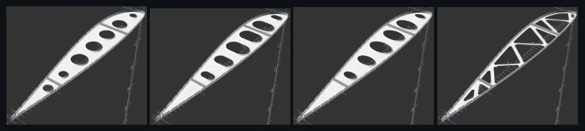
This OpenSCAD-based tool allows homebuilders to generate fully parametric wing rib layouts optimized for FAR 103 compliant ultralight aircraft. Though can be scaled down for RC use. Whether you are modernizing a vintage design or starting a clean-sheet project, this tool handles the complex geometry and engineering constraints of sheet metal rib construction. Though 3D printed models should work just the same.
Key Features
Integrated Airfoil Library: Quickly generate coordinates for common profiles including 4-digit NACA, Clark-Y, and UAK series.
Fully Parametric Design: Adjust chord length, spar placement, and material thickness in real-time.
"Stamped Truss" Mode: Automatically generates a truss-style layout for maximum stiffness-to-weight ratio.
Safety-First Engineering: Built-in assertions for 6061-T6 aluminum ensure your design stays within safe fabrication limits, such as the 20t flange depth limit and 8% material stretch threshold.
CNC & Laser Ready: Export your final layout as a high-precision DXF file for immediate fabrication.
How It Works
This tool is designed to be used by builders, not just coders.
Select Your Profile: Choose your desired airfoil and input your chord length.
Define Your Spars: Set the location and dimensions for your front and rear spars. The tool automatically adjusts the rib geometry to wrap around them.
Layout Lightening Holes: Toggle between Circle, Stadium, or Oval holes. This tool calculates the exact placement to maintain structural integrity while minimizing weight.
Verify Fabrication Specs: The script will alert you in the OpenSCAD console if your flange widths or bend radii are too aggressive for standard 6061-T6. You may need to disable this in the code if you're making an RC rib.
Integration with Flanging Dies
This project is designed to work in tandem with the Parametric Flanging Dies Tool.
Once you have designed your rib and exported the DXF, you can use the exact same hole dimensions in the Die Tool to generate 3D-printable dies that match your rib perfectly. This ensures a seamless "Digital to Physical" workflow for your scratch-build.
Technical Specifications & Safety
Default Material: Optimized for 0.016" (26-gauge) and 0.020" thin aluminum.
Metric & Imperial Support: Includes a toggle for easy unit conversion during the modernization of older plans.
Bend Radius Safety: Standardized to 3t minimum to prevent micro-cracking in the grain of the metal.
Usage Note!
Important:
This tool provides mathematical layouts based on standard engineering formulas. While it includes safety checks for 6061-T6 aluminum, it is the builder's responsibility to verify the structural suitability of their final wing design for their specific aircraft. Please read the disclaimer found in the code!
1. Prerequisites
Install OpenSCAD: Download and install the latest version of OpenSCAD (it's free and open-source).
Enable the Customizer: Once OpenSCAD is open, go to View -> Hide Customizer (uncheck this) to see the easy-to-use parameter sliders on the right side of the screen.
2. Standard Workflow
Select Airfoil: Choose your profile from the dropdown menu (e.g., Clark-Y or NACA 4412).
Set Chord Length: Input your desired chord length in inches or millimeters (use the Units toggle).
Position Spars: Enter the distance from the leading edge for your Front and Rear spars. The tool will automatically cut the spar notches and reinforce the surrounding area.
Configure Lightening Holes:
Select the shape (Circle, Stadium, or Oval).
Adjust the Hole_Spacing to ensure enough material remains between the holes and the spar caps.
Adjust Fabrication Specs: Set your Metal_Thickness (default 0.016") and Flange_Width.
3. Safety Verification
Before exporting, check the OpenSCAD Console (bottom of the screen). The script runs real-time assertions based on 6061-T6 aluminum properties:
Green/Clear: Your design is within safe limits for bending and stretching.
Warnings: If your flange is too deep (exceeding the 20t limit) or the hole radius is too tight, a warning will appear. Do not ignore these warnings, as they indicate a high risk of the metal cracking during fabrication. If you're 3D printing for an RC model, you'll most likely need to comment out or remove the safety check section in the OpenSCAD code window.
4. Exporting for Production
Render: Press F6 to perform a high-quality render of the 2D layout.
Export: Go to File -> Export -> Export as DXF.
Fabricate: This DXF can be opened in any CAD/CAM software for laser cutting, CNC routing, or simply printed at 1:1 scale to use as a paper template for hand-cutting.
Pro-Tip: The "Digital Twin" Workflow
If you are using the Parametric Flanging Dies tool, copy the Hole_Diameter, Flange_Width, and Metal_Thickness values from this layout tool into the Die Generator. This ensures your 3D-printed dies will fit your physical metal ribs with aerospace precision.
Contribute!
Feel free to contribute to this project on GitHub: https://github.com/goney3/openscad-airfoil-rib-layout/
ByRobertoGalloc_356815Likes549Downloads1.8K

 ByWolf_115355Likes513Downloads8.4K

 ByZED4EverLikes313Downloads5.2K

 ByfifindrLikes500Downloads4K

 ByVC_DesignLikes679Downloads3.6K

 ByDan Schwartz SchwartzLikes744Downloads3.4K

 By12_LH_4014475Likes121Downloads162

 ByKNIN_CustomLikes112Downloads433

 ByUpcrid3D_1585693Likes808Downloads2.1K

 ByWilko_SLOLikes935Downloads2K

 BymindthelightLikes251Downloads386

 Bychubbs8697_2027893Likes585Downloads1.7K