



Thùng rác in Vase Mode
 BybobmakesLikes2.5KDownloads17.5K
Build another version of this model.
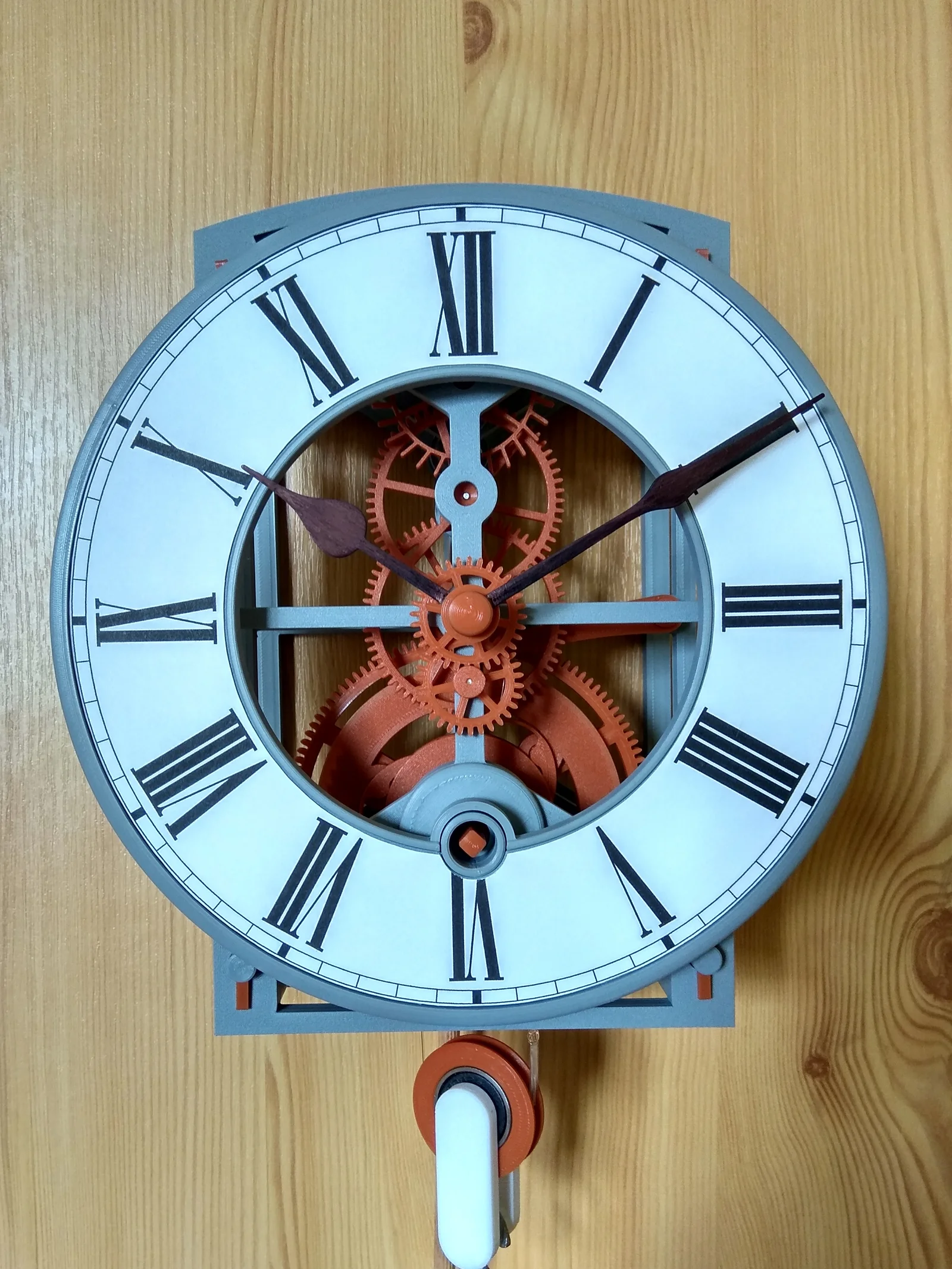
The goal was to create a compact, reliable, accurate and easy to build mechanical clock without any extraordinary modern or futuristic design and shape so they both look nice and have good readability as a common wall clock for your living room.
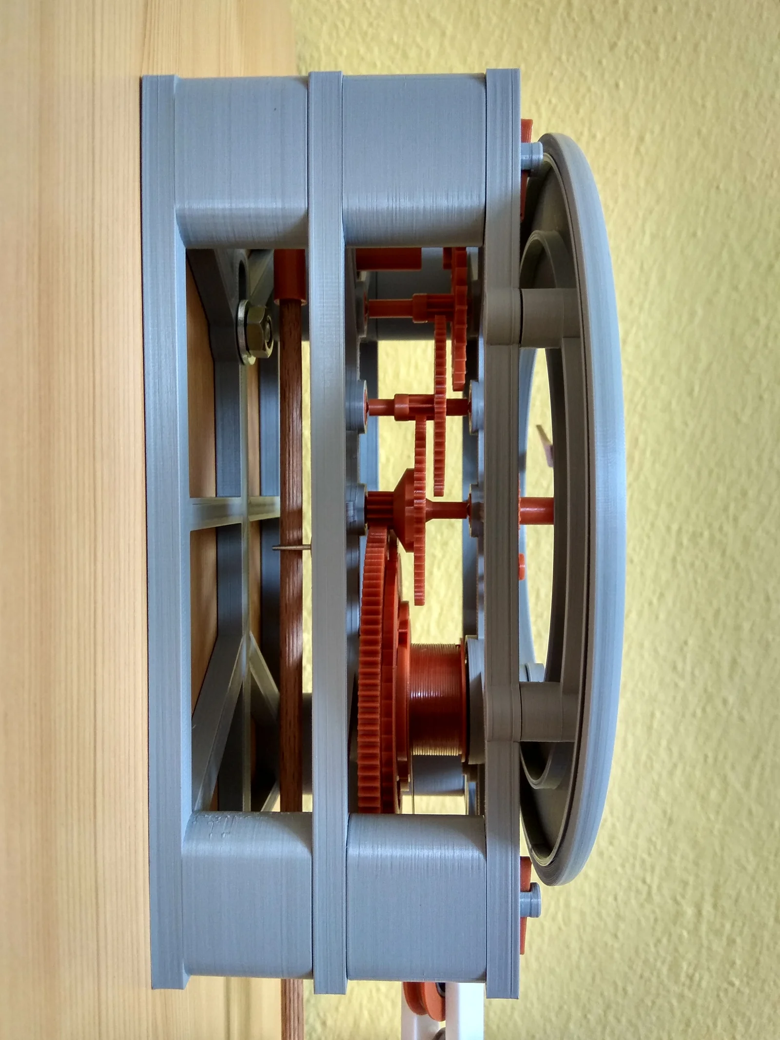
I designed this clock with respect to a classical concept of mechanical pendulum clock: 8 day run time, a pendulum hanging on a spring, cyclodial gears, Harrison mechanism, number of gears and their ratio. Many aspects of the design come up from more than 60 years old book.
All parts should be easy to print and I tried to use as much 3D printed components as possible and if not (such as ball bearings and springs), use some common and not expensive components.
If you have access to a common workshop (at home) you should be totally fine.
Cut the nails (or rods) according to this table:
Length
Quantity
8 mm
10*
10 mm
4
15 mm
4*
20 mm
2
25 mm
2
*3 gear shafts can be made as one part 36 mm long.
Fishing line: roughly 2 m for winding and about 50 cm for the weight (here you can use regular string/cord). I recommend using an “eight knot/loop” whenever is a knot or loop needed.
Ball bearings: Be sure they are clean, without too much grease (you should be okay without any grease).
Wooden rod: Cut it to approximatelly 98 cm, it very much depends on your pendulum weight. It is a good idea to first cut it into a longer piece (or don't cut it at all if you already bought a 1m long rod). Only if the sliding mechanism doesn't allow you to set pendulum position, reduce the rod length even more.
I designed this clock for printing with standard 0.4mm nozzle. However, priting small parts with smaller nozzle diameter is a good idea. Use your standard settings, don't print too fast. Print gears and smaller parts at lower layer height (0.12 or 0.1 mm).
All STL files are in mm.
You can choose among different dial versions:


Or create a custom version for yourself by editing one of these (same for the numerals and hands).
You can also choose whatever color combination you like, I personally like one color for gears and different for other parts.
Part name
STL file name
Qty
Comment
1. Skeleton
Back plate
Back_plate.stl
1
I created version with improved stiffness, but the difference should not be too big.
Back_plate_stiffness.stl
Middle plate
Middle_plate.stl
1
Front plate
Front_plate.stl
1
Cover
Cover.stl
4
Friction bearing
Bearing.stl
8
Front cover
Cover_front.stl
1
Dial
Dial_main.stl
1
Dial outer edge
Outer_edge.stl
1
Use brim.
Dial center
Center_filled.stl
1
Center_empty.stl
Use brim.
Center_hex.stl
Center_pattern1.stl
Looks cool when printed on glass bed.
Pin
Pin.stl
4
2. Gears
2.1 Main shaft
Shaft
Shaft.stl
1
Use at least 5 perimeters. If making out of steel, see drawing bellow.
Washer
Washer.stl
2
Main wheel
Main_wheel_120.stl
1
Ratchet wheel large
Ratchet_wheel_large.stl
1
Pawl large
Pawl_large.stl
1
Ratchet wheel small
Ratchet_wheel_small.stl
1
Pawl small
Pawl_small.stl
3
Large pawl stop
Stop.stl
1
Drum
Drum.stl
1
2.2 Minute shaft
Minute wheel
Minute_wheel_64_12.stl
1
Locking nut
Locking_nut.stl
1
Rotating part
Rotating_part.stl
1
2.3 Third shaft
Third wheel
Third_wheel_60_8.stl
1
Extension tube 1
Tube1.stl
1
2.4 Escape shaft
Escape wheel
Escape_wheel_30_8.stl
1
Extension tube 2
Tube2.stl
1
2.5 Pallet shaft
Pallet shaft
Pallet_shaft.stl
1
Pallet
Pallet_exact.stl
1
Only for precise printing or machining like SLA.
Pallet_not_finished_yet.stl
Pallet making tool
Pallet_tool.stl
1
Pallet_tool_nut.stl
1
Pallet nut
Pallet_nut.stl
1
Crutch
Crutch1.stl
1
Connected together
Crutch2.stl
1
Crutch nut
Crutch_nut.stl
1
2.6 Hand mechanism
Pinion 10
Pinion_10.stl
1
Wheel 1
Wheel_30_8.stl
1
Tiny washer
Tiny_washer.stl
1
Wheel 2
Wheel_32.stl
1
Tiny stop
Tiny_stop.stl
1
Hour hand
Hour_hand.stl
1
Minute hand
Minute_hand.stl
1
3. Pendulum
Pendulum spring
Pendulum_spring.stl
1
Use at least 4 perimeters.
Hook
Hook.stl
1
Connector
Connector.stl
1
M6 rod
M6_rod.stl
1
M6 x 80 mm threaded rod
Pendulum bob part 1
Pendulum_bob_1.stl
1
Pendulum bob part 2
Pendulum_bob_2.stl
1
Regulating nut
Regulating_nut.stl
1
4. Winding handle
Handle
Handle.stl
1
Handle knob
Handle_knob.stl
1
Handle screw
Handle_screw.stl
1
5. Weight
Pulley body
Pulley_body_1.stl
1
Pulley_body_2.stl
1
Pulley caster
Pulley_caster.stl
1
Put on 608 bearing.
Top part
Weight_top.stl
1
Drill the hole in case you use a wider cord.
Bottom part
Weight_bottom.stl
1
Pin
Pin_6mm.stl
1
Can be made out of Ø4-6mm wooden rod (lenght 30 mm)
Tube
Weight_tube_{length}cm.stl
1
You really don't need to print this. Just use thick paper and make a custom length tube.

Figure: Shaft nominal dimensions.
Slicing gears: Be sure to always check a printing path! In case it looks like this:

check “avoid crossing perimeters” in Prusaslicer. This will probably cause stringing and bad surface finish, you really have to prevent this. Good result should looks like this:

Also disable thin wall detection if it looks like this:

Good slicing:

Another challange is to print without elephant foot, that will cause incorrect tooth geometry and larger friction. Feel free to play with elephant foot compensation and maybe set value a bit larger than usual.
Slicing skeleton: Use at least 4-5 or even more perimeters, otherwise you will have issue with bending and low stiffness.
Printing the escapement wheel: Be sure, that teeth are not wider at the tip, good result should look similar to this picture:

Only the pallet needs to be really post processed (until you print the exact version on SLA printer). To make this process easy, I modeled a tool with the exact dimensions. Make the faces smooth and flat. No burr should be there. Finished pallet should look like this:


Cross section for a better idea:

Step 1: Preparing the skeleton

Step 2: Main shaft


Step 3: Minute shaft

Step 4: Third shaft

Step 5: Escape shaft

Step 6: Pallet shaft

Step 7: Place the shafts into place

Step 8:

Step 9: Finishing the body

Step 10: Pendulum

Step 11: Weight

Step 12: Winding handle

Finally push the fishing line through the pulley and make loop at the end (don't cut it yet, you may find out that you need to move the loop a bit further). Hang the loop onto a small stump on the front plate (from behind).
Hopefully, modeled keyhole should work just fine as it is common way of hanging stuff on a wall. Now you can hang the weight on the pulley and wind the clock by rotating the handle clockwise.
Just carefully push the minute hand to set the time. Try moving only forward, because moving hands backwards might stop the clock.
First of all, don't care about your pendulum length. You have to make your clock create regular tick tock sound. If you hear something like “ticktock-pause-ticktock-pause” move/rotate your clock slightly until you hear the regular sound.
Is your clock running? If so, congratulation! (If not, see issues below) Now you want to make your clock run accurate. To do so, longen or shorten you pendulum with adjusting nut at the bottom of the pendulum bob. You can use trial and error method or if you want play with math yourself, just use this well-known equation (linear aproximation for small angle)

where T=2 s, g~9810 mm/s^2 (for Czech Republic) and l is the length (in mm). To make this process easier, you can use my short script in COLAB, which uses the expression above (currently only in czech language).
Possible issues: Your clock is not running or you have similar problem. Don't give up. The issue is ussualy one of the following:
That's it! Your clock should be running. I hope you like my design.
In long term of use, you may have
BybobmakesLikes2.5KDownloads17.5K

 Byquibeck_3353173Likes1.5KDownloads11.5K

 ByKittenRaeeLikes381Downloads904

 ByHuyluy_1057304Likes176Downloads421

 By3DWizardry_1270392Likes295Downloads744

 Bym-collectableLikes0Downloads3.9K

 ByAndrei_817503Likes319Downloads721

 ByJiri3DLikes319Downloads600

 ByTommy3DLab_2023125Likes636Downloads2.5K

 Bymoleculecrtr_1215658Likes544Downloads2K

 By178222178222_2484344Likes449Downloads1.7K

 ByEldordLikes499Downloads1.4K