



Cable Mount - Kẹp Giữ Dây Cáp (Có Lỗ Bắt Vít)
 ByVC_DesignLikes271Downloads753
Build another version of this model.
Hope this model will be helpful. If you liked it please hit the [🧡 Like] button.
While working on some projects I encountered with a scenario where I needed to make a simple circut for LEDs, which requires a resistor component along with soldering and isolating procedures.
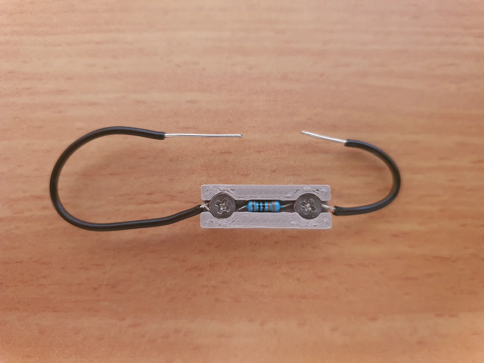
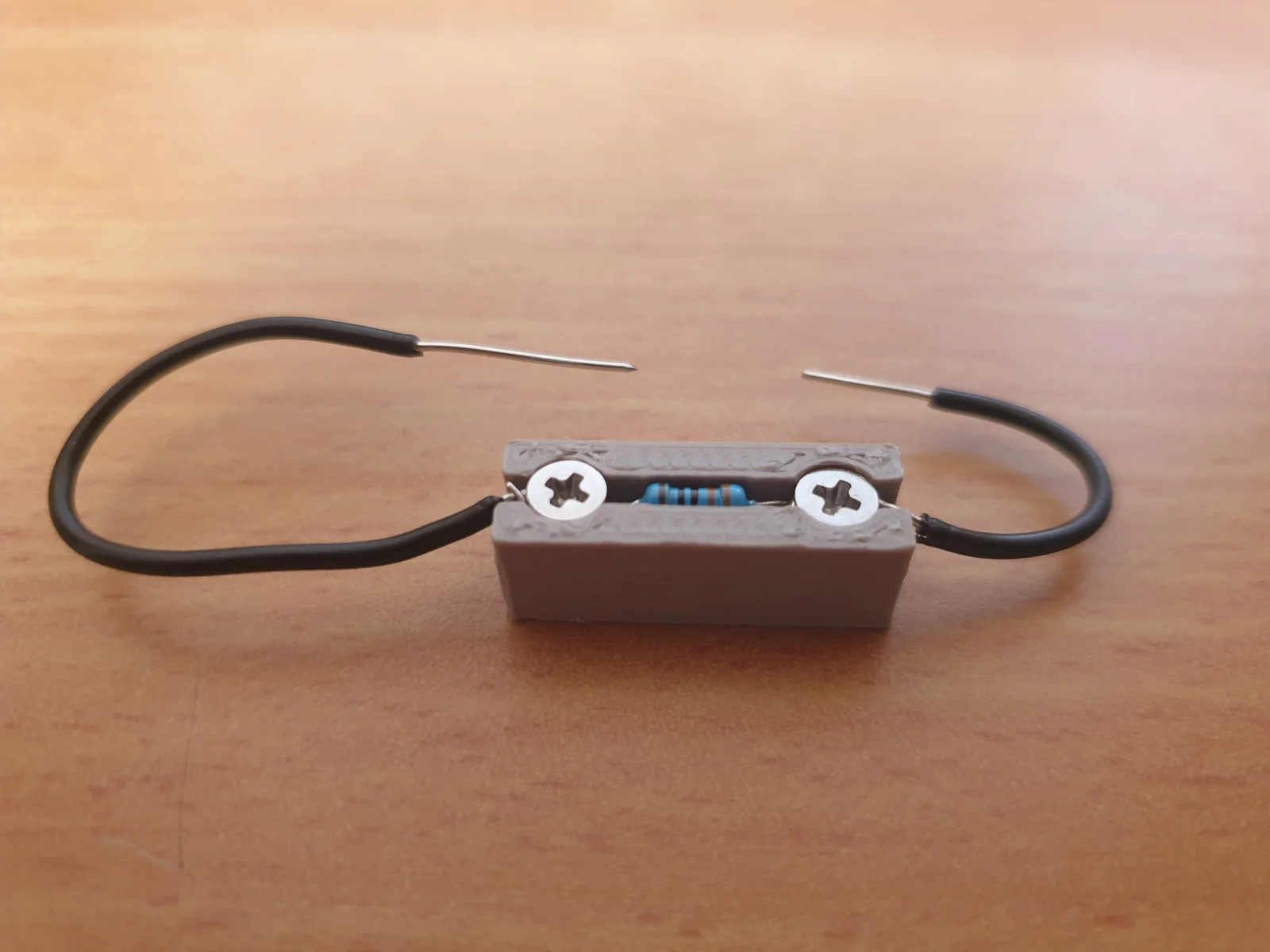
Since I didn't want permanent soldering together of my components, I came up with this simple design of a 2-wire-connector box which works with screws to hold up the wires. I also designed a small socket between the 2 screws for a resistor to sit tight in-between.
For Using it without a resistor:
For Using it with a resistor:
To isolate the circut I also made 2 lid versions to fit above the box; one version has a small tooth above the channel on each side where the wires are inserted, which make a nice grip on them, though it is also less easy to disassemble once you put it on. Hence, I made a second version without the grip teeth which you can easily slide ontop the box from the side, without needing to stretch the side walls.
Please note that I designed it to work with M2.5 screws diameter which goes well with the Raspberry Pi. This specific design is for the 6mm screws size. Other screws may also work but their heads may not fit flushed with the box and so the lid may not fit.
No support is needed. I included my Prusa Slicer files where I already rotated the lid to be printed on its side so no support will be needed. If however you use the stl files, make sure you rotate the lid to be printed with one of its small sides facing down.
ByVC_DesignLikes271Downloads753

 ByFredlPrintLikes144Downloads180

 ByZED4EverLikes313Downloads5.2K

 ByMatthew_GhostLikes350Downloads939

 ByfifindrLikes500Downloads4K

 ByExtrutimLikes0Downloads183

 Bymrfixit_324954Likes65Downloads473

 ByDan Schwartz SchwartzLikes744Downloads3.4K

 ByBrokentooth_designsLikes83Downloads449

 Bydawid-ku-akLikes0Downloads104

 Byvc-designLikes0Downloads3.2K

 ByUpcrid3D_1585693Likes808Downloads2.1K