
F3D
Thước Khuôn Quân Sự "Commander's Ruler" LD-1 (Bản Remake) 1

4 images

Đồ Gia Dụng

Thước Khuôn Quân Sự "Commander's Ruler" LD-1 (Bản Remake)

By GuillaumeBlr_510797

Downloads
243
Likes
69
Views
1,565

Files 8 9.4 MB

  • A_02mm_245mm_color_1777030033.3mf3MF · 1 MB
  • A2_02mm_245mm_color_extra_transparency_1777030034.3mf3MF · 539 KB
  • B_02mm_245mm_mono_1777030035.stlSTL · 2 MB
  • C_04mm_245mm_mono_1777030039.stlSTL · 721.2 KB

Make a variant with AI

Build another version of this model.

Open Studio

Description

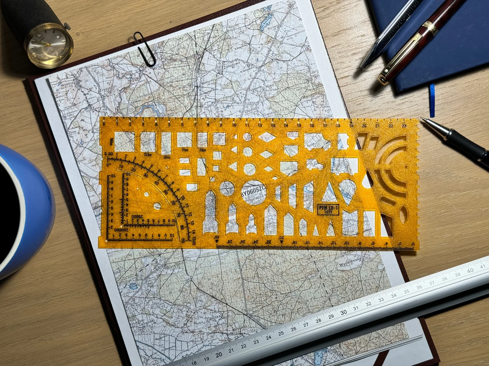
This is a remake of a vintage template produced in Poland in the '70s by the Tracing Instruments Manufacturing Facility in Paczków. I got mine from my grandpa, and it was a ton of fun back in the day. I’m pretty sure at least half of polish population had or at least saw it :)

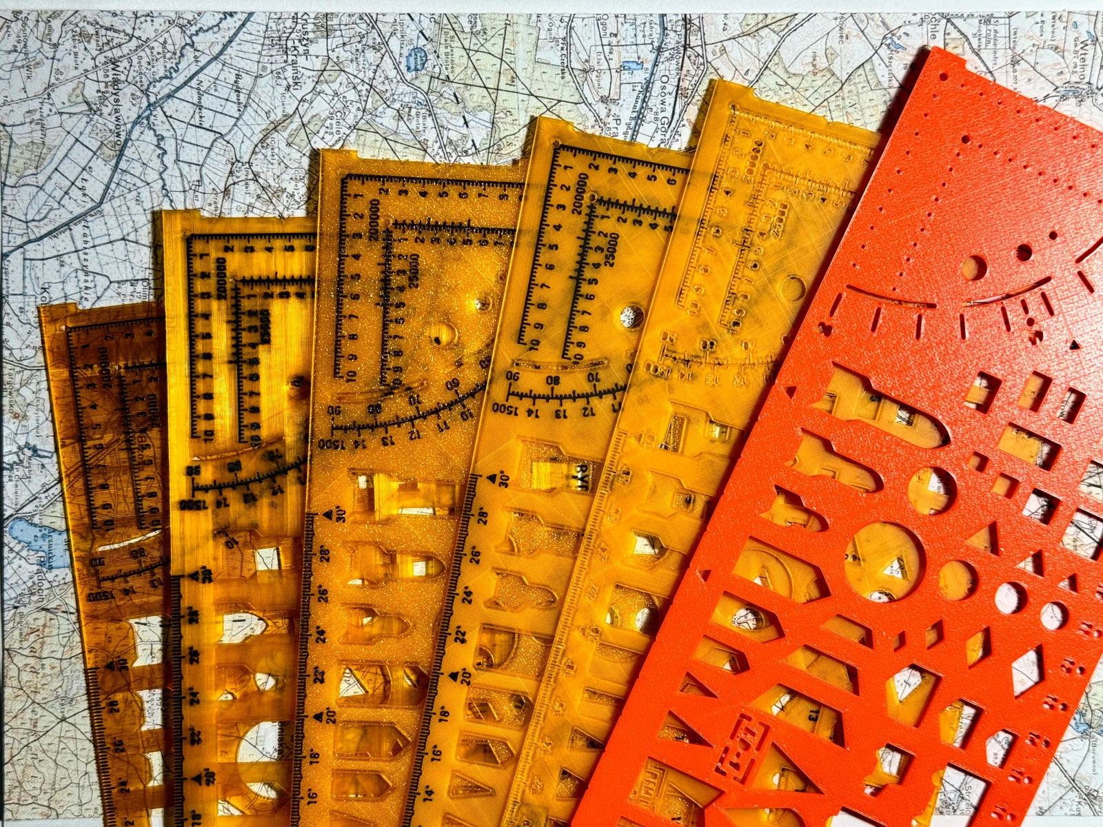
There are five versions:

  • A) default For 0.2 mm nozzle, larger printer, and multicolor - closest to the original (no extra transparency, used for cover photo)
  • A2) For 0.2 mm nozzle, larger printer, and multicolor - with protruding markings to allow extra transparency on the main plate
  • B) For 0.2 mm nozzle, larger printer, and single color
  • C) For 0.4 mm nozzle, larger printer, and single color - this was actually the first prototype
  • D) For 0.4 mm nozzle, mini printer, and single color - I didn't forget about you, no worries!

No model for multi-color 0.4, sorry.

Please read the recommended print settings to avoid hassle.

General recommendations:

  • Layer height: 0.1mm
  • Material: Base - transparent orange PETG; Markings - any black PETG
  • Speed: This is a detailed model. I usually print it with speeds reduced to around 50% or even 25%, resulting in an 8-10 hour print on A/A2.
  • Infill: 100%
  • Only one wall on first layer: enabled
  • Walls: 1-2
  • Top & Bottom Shells: 1-2
  • For 0.4 mm prints (models C and D) set X-Y hole compensation at 0.1mm. I found slightly larger cut-outs are better suited for writing through them.

For extra transparency (mostly sourced from other recommendations):

I wasn't able to get it perfect, especially when combining with the precision of markings within the plate - these tend to dissolve, and generally more artifacts would appear. Therefore, I created an additional version (A2) with protruding markings. It's still far from perfect - for example, there are still prominent over-extrusions within small perimeters of a plate, as well as infill lines are way too visible - so if you don't care for extra transparency, stick to model A with the general recommendations.

  • Build Plate: Smooth
  • Speeds: Layer speeds to 35mm/s or lower; Small perimeters 15mm/s; Small perimeters threshold 6mm
  • Walls: 1
  • Top & Bottom Shells: 0
  • Infill Pattern: Aligned rectilinear, direction 90 degrees
  • Infill/Wall Overlap: 35%
  • Transparent PETG Custom Settings:
    • Flow ratio: 105% of your default (in my case, that was 1.01 ratio)
    • Nozzle temp: 270°C
    • Fan off
    • Top surface flow back to 100% (0.95 in my case)
    • Overrides: Retraction length 3.05mm, Retraction speed 30mm/s, Wipe distance 3mm
  • No custom settings for black.

If you are able to achieve better transparency results with default (A) model, I'd love to hear about it! Thanks in advance!

Model Orientation:

  • A, B, C, and D: Face down for the best finish.
  • A2: Face up for protruding markings.

Project Files:

  • A and A2: Projects for a slicer.
  • B, C, and D: Just STLs, as they are not assembled nor require any special treatment (apart from general recommendations).
  • srcAa, srcAb, srcAc: STLs if you feel like assembling it yourself

Hope you like it!

Read more Show less

Print spec

Formats
3mfstl
Model files
8
Total size
9.4 MB
Largest file
2.3 MB

0 comments

See all