



Chân Đế Loa Tùy Chỉnh (Customizable Speaker Stand)
 ByAdam Záhořák ZáhořákLikes39Downloads251
Build another version of this model.
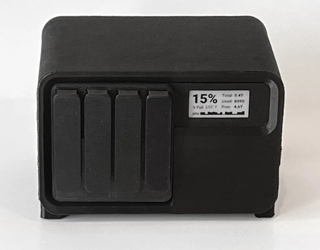
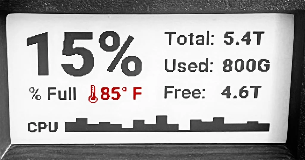
This remix combines the two part case into one, adds an e-Ink display window with the Pimoroni InkyPHAT display, and adds additional mount points for 40mm case fans. All other files are the same, but they have been converted to STL for easier printing. This remix is subject to change as I make a more elegant back panel that fits the hardware I am using. Right now it's just a rectangle cutout as I work out the best way to enclose the cables. I will also add more detail to the assembly instructions as I go.
This is a fairly easy project but it has a lot of steps. It’s also a bit expensive to produce given the price of the four SATA drives. You do not have to use the same components I used, but where you make changes, you’ll need to account for the differences. If you use cheaper drives, there should not be a significant difference in setup other than cost. I used the Samsung EVO 2tb SATA drives because I already had them for a different project. It does not fundamentally matter what hardware you choose.
Raspberry Pi 5 4gb + Active cooler + pro endurance SD card
Raspberry Pi Zero 2w (with headers) + regular SD card
Four 2tb SATA SSD Drives (Samsung 870 EVO)
Pimoroni red InkyPhat e-ink display
Geekworm x1009 SATA hat with power adapter
Fans
Temperature sensor
USB Ethernet adapter
Print all pieces (this will take a few days). Print all with supports (everywhere) in the orientation that they appear.
Install a basic Raspberry Pi Lite OS onto an SD card and configure it for Wifi (you’ll need an ethernet cable later but for now we can do our config over wifi)
Install 8 heat set inserts into the top and bottom holes of the raspberry pi sled
Mount the raspberry pi on the sled using standoffs
Install the Geekworm SATA hat and follow the instructions
Install the temperature sensor and follow the instructions here
Optionally print the mounting bracket for the breakout board and install it with screws
Mount the sled into the case from the bottom using M2.5 screws (optional but recommended)
Plug in the SATA drives in order starting from the left (0) to (3) if using right angle cables, the last drive should be mounted with the right angle bracket going into the raspberry pi while the other three cables will have the right angle brackets going into the drives. This is because it doesn’t fit any other way and I didn’t want to mod the case again, so I just reversed the cable.
Plug in the SATA power cable to the Geekworm Hat
Do not power the raspberry pi yet
Optionally glue the breakout board mount to the case (but really it’s better to wait until near the end for this step and honestly I didn’t glue it, it’s just hanging out in there loose
Thermal sensor should go in the open space behind the SATA cables but in front of Zero 2W
Follow the instructions from Pimoroni here to setup the InkyPhat display: https://github.com/pimoroni/inky
At this point you should have all the cables connected. Power up the raspberry pi using the Geekworm power supply (not the USB port, which will not be used)
Setup raspberry pi 5
Install Geekworm SATA hat drivers https://suptronics.com/Raspberrypi/Storage/x1009-v1.1_software.html
sudo nano /boot/firmware/config.txt
Enable the PCIe external connector dtparam=pciex1 dtparam=pciex1_gen=3 # note this is not officially supported but it does work on my Samsung drives
sudo rpi-eeprom-config -e Add PSU_MAX_CURRENT=5000 at the end of the file
sudo reboot
sudo lspci
Install the temperature sensor
Hardware setup https://www.youtube.com/watch?v=j7LLVkPpQ78&t=199s
Written instructions https://piddlerintheroot.com/temp-sensor-ds18b20/
Software setup
Sudo rasp-config
My setup (differs from the video)
Green = Ground > Black Blue = Live > Red Purple = Data > Yellow
Purple goes to pin 4
sudo nano /boot/firmware/config.txt
Add this line to the bottom of the file to enable the 1-wire interface
dtoverlay=w1-gpio
Reboot
sudo modprobe w1-gpio sudo modprobe w1-therm
Confirm that the sensor is working
Setup OpenMediaVault
Install open media vault Format disks Install md plugin Create RAID 5 Array Create file system Bridge Ethernet connections (if using) Install and enable the thermal logger and thermal server scripts Install and enable the CPU logger and CPU server scripts Install and enable the RAID monitor service
Setup raspberry pi zero w
Sudo raspi-config
Reboot
Connect to Wifi (or as a USB gadget, but I have not been able to get this running yet) Install the drivers for the InkyPhat Test the screen to ensure connectivity Install the NAS.py script Setup crontab to run the NAS.py script every x minutes
Install the back cover with four medium length M2.5 screws
Clone this repo into both the Raspberry Pi 5 and the Raspberry Pi Zero 2w. (Note: more specific instructions to come as I edit this file.)
https://github.com/adunderwood/RaspberryPi_NAS
SSH into the nas Copy the services to /etc/systemd/system Sudo systemctl daemon-reload Start services
Install Pimoroni drivers source source.sh pip install requirements python nas.py crontab -e
/5 * /bin/bash -l -c "source /home/nas/.virtualenvs/pimoroni/bin/activate && python /home/nas/display/nas.py"
^ adjust the paths to reflect your configuration. This uses the default virtual environment created by the Pimoroni driver installation.
Category: Electronics
ByAdam Záhořák ZáhořákLikes39Downloads251

 ByZED4EverLikes313Downloads5.2K

 ByBrokentooth_designsLikes83Downloads448

 ByWilko_SLOLikes935Downloads2K

 ByWolf_115355Likes513Downloads8.4K

 ByVC_DesignLikes271Downloads750

 ByfifindrLikes500Downloads4K

 Bymrfixit_324954Likes65Downloads472

 ByDan Schwartz SchwartzLikes744Downloads3.4K

 Bydona3d_Likes456Downloads675

 ByUpcrid3D_1585693Likes808Downloads2.1K

 ByJordanK_858807Likes42Downloads430