



Thùng rác in Vase Mode
 BybobmakesLikes2.5KDownloads17.5K
Build another version of this model.
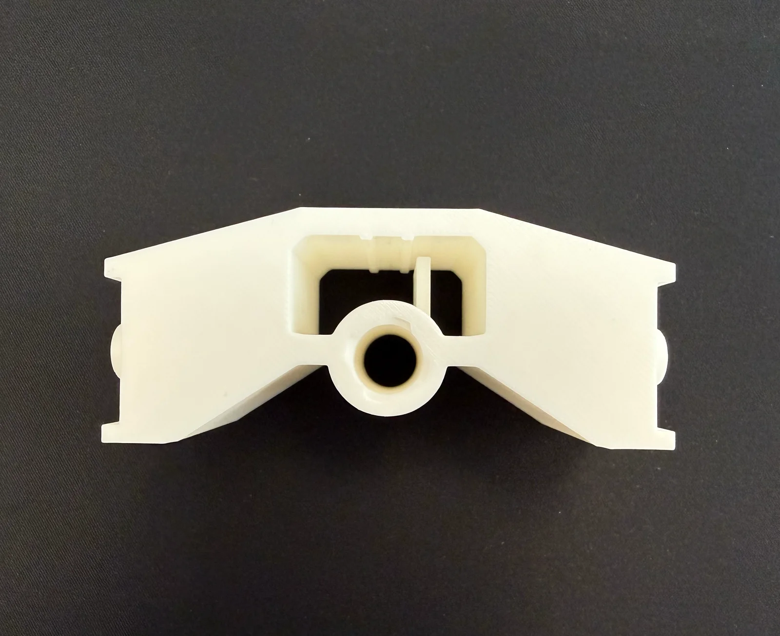
Recliner Actuator Block Replacement - MotoMotion / MOTO / HHC Power Recliners
A 3D-printable replacement for the arched actuator moving block (also called "slide block" or "traveling nut") found inside the linear actuator of power reclining sofas. This is the plastic block that rides on the worm/lead screw inside the actuator tube and connects to the legrest linkage. When it breaks, your legrest stops working.
This part is nearly impossible to buy in the US. The only known source for the generic block is SofaRehab in Australia, but even that version has the wrong thread pitch for many actuators.
Sofa manufacturer: MotoMotion Vietnam (HHC/MOTO brand)
Internal sofa code: E01001188A 3 XS8046DG02-6-RX1 0019
Mechanism family: XS8046DG02
Actuator:
Brand: MOTO / HHC
Model: LMD12517W1-4-H
Specs: 24 VDC, 5A, 311mm stroke, 1000N max load, 38mm/s
Connector: 5-pin MOTO/HHC control plug
If your sofa has a similar feature set and a MOTO/HHC actuator (any LMD12517W variant), this block should work for you.
Actuator Block Dimensions
Dimension
Value
Width (wing tip to wing tip)
96 mm
Height (arch peak)
42 mm
Depth (front to back)
40 mm
Lead Screw Thread Specification (CRITICAL)
This is the part most people get wrong. The lead screw inside MOTO LMD12517W actuators is NOT a standard single-start thread.
Spec
Value
Thread type
Metric Trapezoidal (TR)
Major diameter
14 mm
Pitch
3 mm
Starts
4 (four-start)
Lead (travel per revolution)
12 mm
Thread angle
30°
How to verify your screw matches:
Measure peak-to-peak diameter with calipers → should be ~14mm
Measure distance across 10 adjacent thread crests → should be ~30mm (pitch = 3mm)
Look at the end of the screw; count how many separate grooves spiral off → should be 4
Or: print the included test nut and try threading it on
The steep thread angle that makes it look "wrong" compared to normal screws is because it's 4-start — four independent helixes wrapped around the rod. This is common on fast-travel actuators (mine is 38mm/s).
actuator_block_TR14x3_4start.stl - Complete block with TR14x3 4-start internal threads.
test_nut_TR14x3_4start.stl - Small hex nut for verifying thread fit before committing to a full print.
thread_cutter_TR14x3_4start.stl - Male threaded rod for boolean subtraction in CAD software (for making your own custom block).
actuator_block_TR14x3_4start.step - Full block with threads, editable in Fusion 360, SolidWorks, FreeCAD, or any CAD that reads STEP.
actuator_block_NO_THREADS.step - Block body only, no threaded bore. Use this if your screw has a different thread spec; import the thread cutter STL (with modified parameters) and boolean-cut your own threads.
TR14x3_4start_test_nut.scad - Parametric test nut. Change major_d, pitch, starts, and clear to match your screw. Requires BOSL2 library.
TR14x3_4start_thread_cutter.scad - Parametric threaded rod for boolean cuts in CAD. Same adjustable parameters. Requires BOSL2 library.
⚠ OpenSCAD files require the BOSL2 library: Download from https://github.com/BelfrySCAD/BOSL2 and place in your OpenSCAD libraries folder. Without BOSL2, the files will not render.
If your actuator is different from mine, you need to figure out your own thread before printing.
Use calipers across the screw, peak-to-peak. Rotate the screw to find the maximum reading (both jaws on peaks, not valleys).
Mark a thread crest. Count 10 crests forward. Measure the distance between mark #0 and mark #10 with calipers along the screw axis (not angled). Divide by 10 = pitch.
Look at the cut end of the screw straight-on and count how many separate grooves spiral off. Or: mark one groove with a Sharpie, trace it for one full revolution, measure how far it traveled axially. Divide that distance by the pitch = number of starts.
Open the .scad test nut file, enter your measured values, render, export STL, print, and try it on the screw.
Print Settings
Setting
Recommended Value
Material
PETG, PC Blend, Nylon, or CF-Nylon. No PLA. It will creep and crack under load.
Layer height
0.15 - 0.20 mm or less
Nozzle
0.4 mm
Perimeters / walls
5-6 minimum
Top/bottom layers
5-6
Infill
50-85%, Gyroid pattern
Print speed
30-40 mm/s (slower = better threads)
Orientation
Bore axis vertical (flat bottom on bed, arch facing up)
Supports
Yes for the arch overhang, but use a support blocker over the threaded bore to keep supports out of the threads
Z-seam
Paint away from the threaded bore area
Cooling fan
Lower than normal (30-40%) for better thread surface quality
If you need to modify the block shape but keep the threads:
Open your custom block design in Fusion 360
Insert → Insert Mesh → select thread_cutter_TR14x3_4start.stl
Position it centered on the bore, aligned with the bore axis
Mesh tab → Modify → Convert Mesh (select Parametric)
Modify → Combine → Target: your block body, Tool: the converted thread body, Operation: Cut
Export as STL for printing
If Convert Mesh fails due to high polygon count, open the .scad file, reduce $fn from 72 to 48, and re-export.
Many recliner actuators use similar but not identical lead screws. Common variations:
Screw
Pitch
Starts
Lead
Notes
TR14×3, 4-start
3mm
4
12mm
This model — MOTO LMD12517W
TR14×3, 1-start
3mm
1
3mm
Common on slower actuators
TR14×4, 1-start
4mm
1
4mm
Common on Kaidi/RMT actuators
TR10×3, 1-start
3mm
1
3mm
Smaller actuators
~9/16" ACME
~3.2mm
1
~3.2mm
Imperial actuators (rare)
Use the OpenSCAD files to generate test nuts and thread cutters for any of these specs. Just change major_d, pitch, and starts.
I accidentally broke the actuator block on a MotoMotion multimedia recliner. The part is not sold individually by the manufacturer or any US retailer. The only known source (SofaRehab, Australia) sells a generic block with the wrong thread pitch for this actuator. Amazon sells complete actuators with similar-looking blocks, but those also have wrong thread specs for MOTO LMD12517W actuators.
After extensive research, caliper measurements, and multiple failed test prints, I identified the thread as TR14×3 4-start metric trapezoidal; not a standard single-start thread. The steep helix angle is what makes it look "wrong" compared to typical lead screws and is the reason off-the-shelf replacement blocks don't thread on.
The block was modeled in Fusion 360 using reference photos as canvases, with caliper measurements for all critical dimensions. The internal threads were generated in OpenSCAD using the BOSL2 library and boolean-subtracted in Fusion 360.
Tags / Keywords
recliner, power recliner, actuator, linear actuator, MOTO, HHC, MotoMotion, LMD12517W, LMD12517W1-4-H, actuator block, slide block, moving block, arched actuator block, traveling nut, lead screw nut, TR14x3, trapezoidal thread, 4-start, four start, worm gear, legrest, footrest, XS8046DG02, recliner repair, sofa repair
BybobmakesLikes2.5KDownloads17.5K

 Byquibeck_3353173Likes1.5KDownloads11.5K

 ByHuyluy_1057304Likes176Downloads418

 ByTommy3DLab_2023125Likes636Downloads2.5K

 Bymoleculecrtr_1215658Likes544Downloads2K

 By178222178222_2484344Likes449Downloads1.7K

 ByEldordLikes499Downloads1.4K

 ByVaclav_ZahradkaLikes181Downloads1.2K

 ByScooLikes35Downloads180

 ByowlartLikes527Downloads1.3K

 Bywbphelps_250497Likes14Downloads144

 Bytjfenwick_306961Likes385Downloads1K