


Khay Đựng RAM (DIMM/SODIMM) Xếp Chồng Tiện Lợi Cho Góc Làm Việc
 ByJwidessLikes34Downloads379
Build another version of this model.
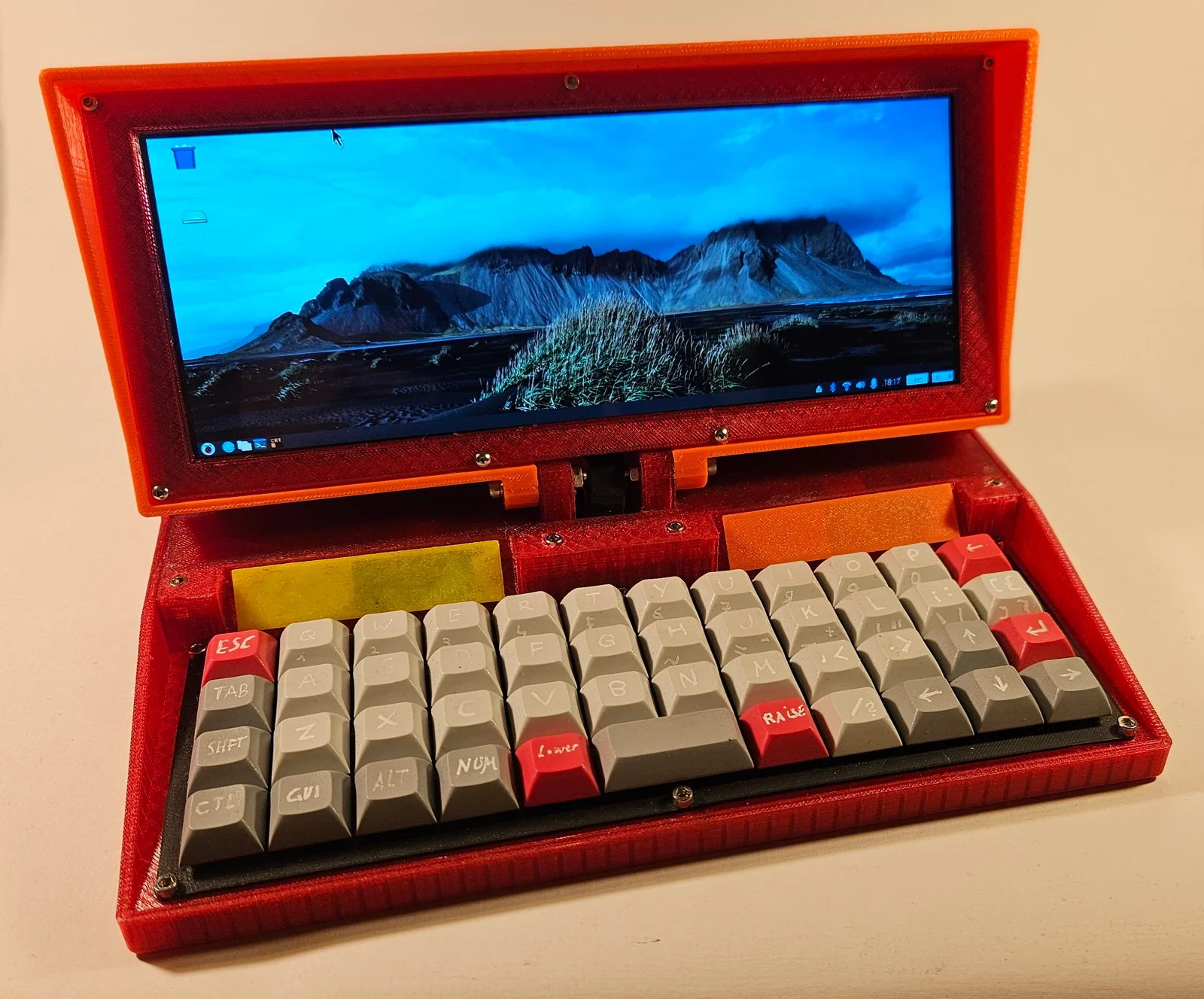
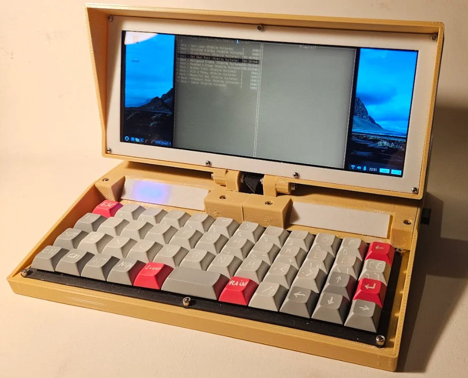
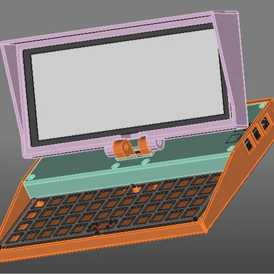
This is my Portable Raspberry PI 4 computer. Important for the product was that it has a mechanical keyboard. The rest of the design is worked around this keyboard.
Included is the Freecad Project and Step files.
Some kind articles:
https://hackaday.com/2024/07/28/printed-portable-computer-inspired-by-the-classics/
If you like my Design maybe consider:
https://buymeacoffee.com/ironatmmi
Print Size:
For the interfaces in the front and the back you should design you own panels for your needs.
Example:
Red button connect to the battery boot button (Momentary)
Black button connect to the On/Off Switch of the battery (Switch)
Audio stereo Jack
USB C to load the Battery
Second HDMI out
Left red button Activate Battery Indicator (Switch)
Symbolic Picture. Has changed already: No dupont cable for Pi power. See further down for more information.
On/Off switch and Power is mandatory.
Battery checker connection is a Bonus.
I am not sure what boot should do.
As you can see I have done connectors on every cable to make assembly and disassembly easier.
For the Power cable refer to part list. (I have used dupont but the Pi was rebooting)
This battery hat have had pogo pins that I have had to remove. (Snipping it)
I was able to unsolder the 5V pogo pin. The other I was not able to, so i soldered directly on the remains. I was not able to use SDA/SCL connection successfully. (need more investigation)
Power Connector fits fine on pinheader:(Please take care of minus and Plus!)
USB-C for charging.
USB-A is used for the Display.
On/off Switch Button is soldered in most left pin and middle. (not the mechanical part of the switch)
The Keyboard is based on the 40 % Happy key, but the PBC with the 2040 Raspberry will not fit in the case (Height and port position). You may relocate the 2040 Pi and wire it with the PBC. I have printed the included Keyboard Casket and handwired the Keyboard. Is easier than you think. (Little Video) For the keyboard software I use Circuit Python with KMK.
Build:
Print the Casket:
Parts:
Silverwire, Solder&Soldering Iron, Diodes, Keyswitches and patience. And Some wires and the Pico2040 board.
Snap the key switches in.
Solder
Solder wires to columns and rows and connect them to the Pico 2040
Final:
Dont use the presoldered 2040 Board with the PCB. It will not fit. But you may solder wires to the PCB and relocate the 2040 Board.
The code.py configuration is included. You may need to take care of the row and column gpio configuration.
# Cols
keyboard.col_pins = (board.GP6, board.GP5, board.GP4, board.GP3, board.GP2, board.GP1, board.GP12, board.GP11, board.GP10, board.GP9, board.GP8, board.GP7)
# Rows
keyboard.row_pins = (board.GP21, board.GP20, board.GP19, board.GP18)
The keyboard is wired internally to the Raspberry Pi on the undersite (not a nice job tbh). Therefore one USB Port is closed off.
All screws are 3 M except the Raspberry Pi / Battery and screen front panel. They are 2.5 m.
The hinge uses 4 M screws. It is helpful to clue the screws nuts to the hinge.
You will need threaded Inserts for this Project. A lot of them.
This are the parts i used: (Picture Battery is outdated)
This are amazon affiliates links.
US
EU
Display
Keys
KeyCaps
Diodes
Raspberry Pi PICO or Pico clon
compatible with Circuit Python for keyboard
Raspberry Pi 4
Momentary Buttons
Latching Buttons
Power Switch
HDMI Port
Micro USB C Port
Hdmi Cable (2 if you want an hdmi port in the back)
Battery Indicator
(Not that precise but helpful)
Usb-C Connector
(Battery Power)
Battery Hat
(Is ok, but you have to remove the pogopins and solder the connection)
21700 Batteries (2)
Speaker
Stereo Plug
Stereo Port
M 2.5 screws
M 2.5 inserts
M 3 screws
M 3 inserts
M 4 screws
Power Cable for Battery and PI ! Sadly slightly to short. You have to extend it.
Shrinking Tube
Tools:
Soldering Iron
Cables in different colors.
Cabelconnector (Makes assembly and disassemply easier)
For Power delivery use touch input, else the display will not fit into the case.
Speaker Connection:
Connector type doesn't matter, but you will need it while assembly.
Screen Control:
Use double sided tape to stick remote into the groove.
Front Bezel
2.5 M Screews
3 M screews and nuts. Glue nuts to speaker for easier assembly.
If you using 2 HDMI Ports you have to nibble away on the side of the connector to fit booth into the Pi 4.
Black site must always be top.
Use M2 screw's to connect Battery meter.
Most of them Switches have a connector.
Use 2.5 M screws. Route internal keyboard cable (next chapter) to the side.
Use 2.5 M screws.
This is the hardest part. Route all the cables trough the hole in the fontcover. You have then to place the monitor on the back of the case. Route the hdmi cable without connector under the PI. If you have problems with assembly you may use the split front cover.
This covers you can add later after the screen is attached.
Connect HDMI Cable.
Use M3 Screws. Place RP2040 between the hinges in the back.
Insert back panels. It is a press fit.
Connect the Monitor Power to the Battery.
Connect usb-c power for charging.
Connect the internal port to the RP2040
Connect Audio extension Cable. (This is an old print, in the current version you have more space in the front of the PI).
Screw down front cover. Use 3 M screws.
Use M4 screws for hinge. Glue again the nut to the bottom case makes live easier.
Hope you have done enough connector.
Connect Speaker cables. (inner cables are ground/-)
Finalize the build with back cover. Use 3 M screws.
This was the first Design but the there was way to less space for the cables and switches/Ports. Therefore I had to make the back bigger.
For printing you will need support (tree/organic).
Positioning the parts should be obvious. ( Largest Plane down)
Sadly you will need a bigger Printer for the parts at least 256 mm X 256 mm.
Important: I have recognized that the hinge may break with to less infill. I use Prusa Slicer to increase the infill for the hinge:
Main Parts are:
To fit better the screen is rotated upside down. For the Desktop you can set it in the “Screen Configuration”.
For the console itself you have to set it in the
/boot/firmware/cmdline.txt
File: (One line!)
fbcon=rotate:2 video=HDMI-A-1:1600Mx600,rotate=180
Result should like as below:
console=serial0,115200 console=tty1 root=PARTUUID=309f1c16-02 rootfstype=ext4 fsck.repair=yes rootwait cfg80211.ieee80211_regdom=AT fbcon=rotate:2 video=HDMI-A-1:1600Mx600,rotate=180
Added Raspberry Pi Size Battery Holder for M2.5 screws:
Improved the fitting for the “ruthex” threaded inserts.
Some minor improvements.
Fixed screen screw issue so you don't have to edit it in freecad anymore. No it is mounted via a Front Panel.
Updates V29:
Added empty Panels
ByJwidessLikes34Downloads379

 Bylarp3dLikes0Downloads1.4K

 ByJaronLikes310Downloads1K

 Byw3rN42Likes127Downloads938

 BynasikLikes0Downloads227

 Byaka-andyrooLikes0Downloads273

 ByTomDDLikes89Downloads580

 Bysaporra_209519Likes0Downloads6

 Bynodus-designLikes0Downloads109

 ByBroBuilds3D_4455044Likes32Downloads459

 ByckthLikes148Downloads2.4K

 Bynexgen-3d-printingLikes0Downloads397