



Kẹp giữ sợi Filament
 Bytinx_1344834Likes1.2KDownloads6K
Build another version of this model.
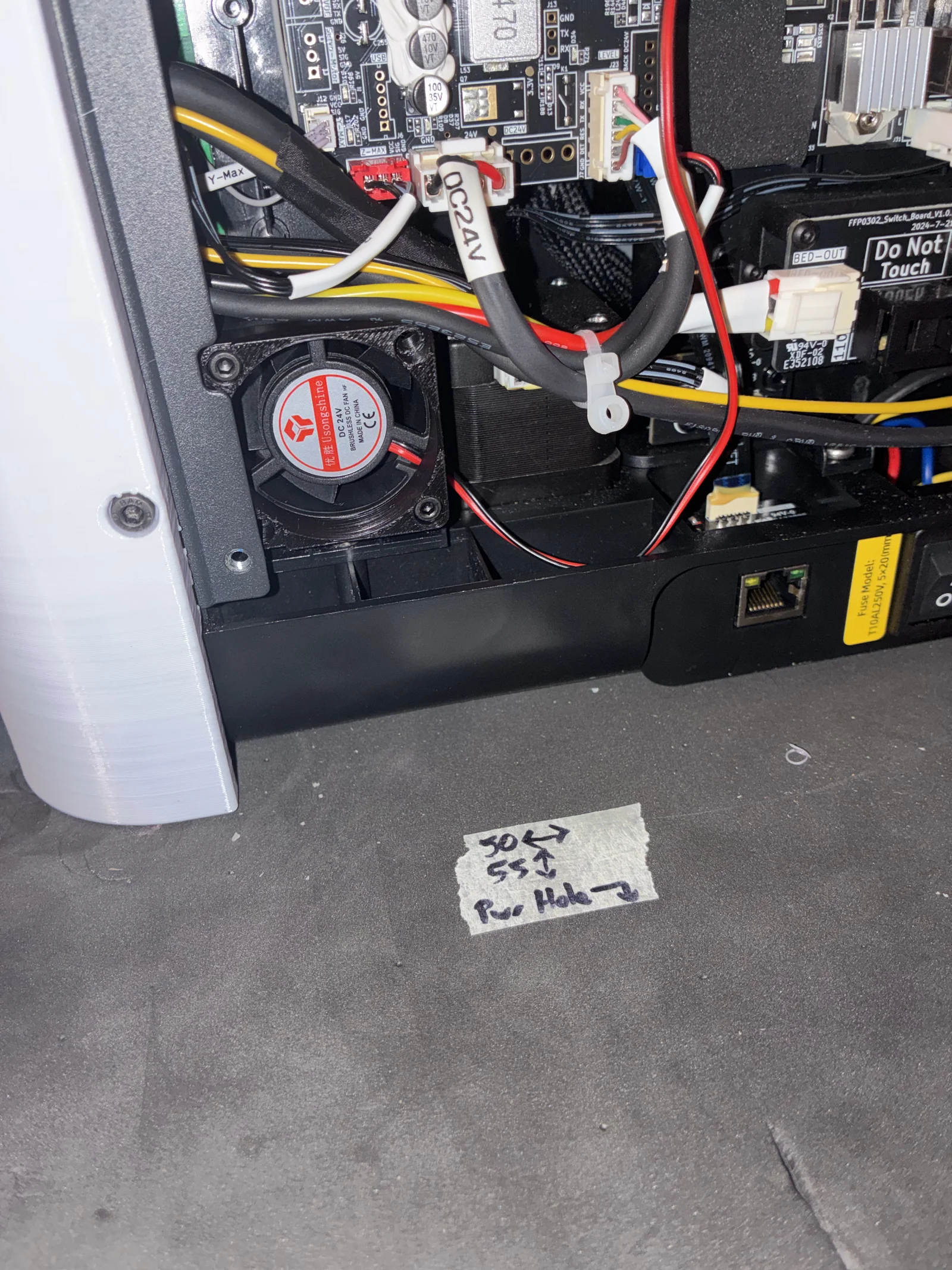
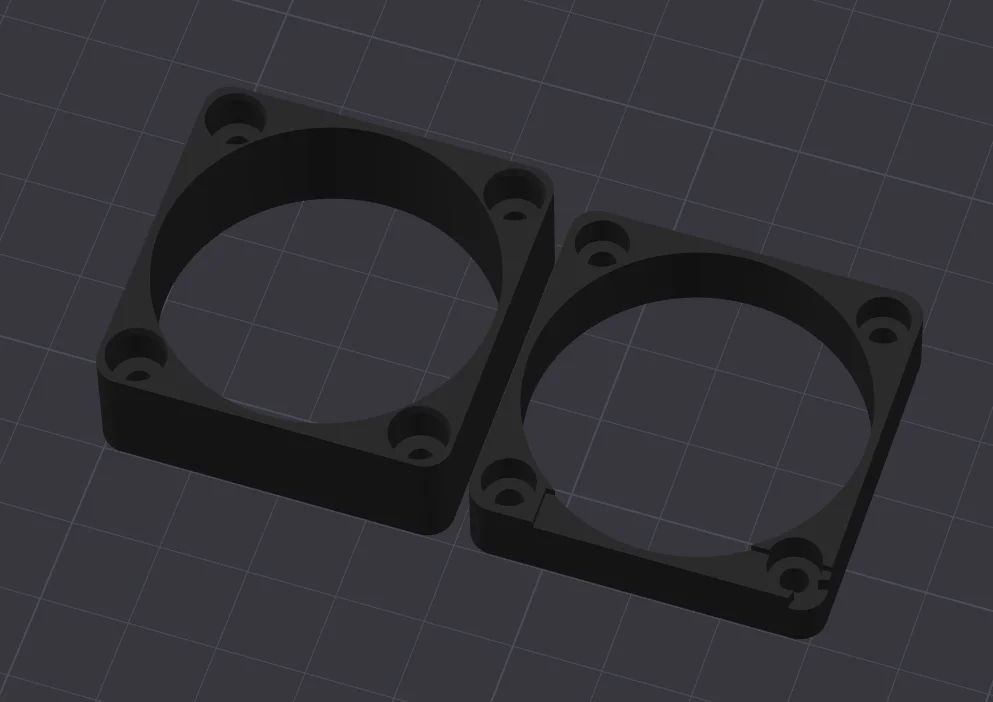
Duct work for adding the exhaust fan (lower filter slot) on an AD5X.
I made this because the two other models I could find for this didn't suit me. One wanted longer screws than I had on hand, and a 4010 fan (I only had 4020's on hand). The other looked annoying both to print and to install. So, I made my own instead.
There are two versions of the "panel side" piece uploaded. One version has room for improvements, but is tested. The other version has the improvements in question, but is untested. If using the one that is not marked "old version", be aware that it may not fit - if you run into issues here, please (a) let me know and (b) use the old version instead in the meantime.
There is also a spacer piece. You'll get a more snug fit with it, but it also makes it trickier to install. I personally didn't use it in the end (despite printing it) but it's there if you want it.
Printing:
- DON'T USE PLA. Ideally use ABS, but PETG should be fine.
- The "Filter Side" piece should be printed upside down. (ie: small holes face-down, large holes face-up)
- No supports or special settings are needed, but Arachne wall generator may be beneficial.
Non-printed parts needed:
- A 4020 fan
- Two M3x16 cap-head screws (preferably self-tapping but don't have to be)
- Two M3x30 screws (ditto)
Installation:
1. Remove the rear cover of your AD5X
2. Carefully lifting the cables out of the way, pop the "Filter Side" piece onto the poles. Use two M3x16 screws - one in the lower left hole, one in the upper right - to secure this piece in place. This piece is rotationally symmetrical, but the side with the smaller holes should face outwards.
3. Place the fan into place, ensuring it's facing the right direction. The caps of the screws from earlier will help line it up.
4. Place the "Panel Side" piece over the fan. This piece must be inserted in the right direction - the recessed edge should be on the left, with the slightly "missing" corner in the bottom left. If you are using a spacer piece, place it between the fan and the Panel Side piece.
5. Secure the assembly together with two M3x30 screws, in the top-left and bottom-right holes.
6. Connect your fan to its power source.
How to power the fan is left as an exercise for the reader. One option could be using the LED port on the motherboard, if the fan wiring's polarity matches the LED port (or if you are able to rewire it to do so).
I don't charge for my functional models. If you want to support my work, buy a Ninjr from my paid models: https://www.printables.com/@Trumble/store
Bytinx_1344834Likes1.2KDownloads6K


 Bynamida-verascheLikes0Downloads155

 Byprusa-researchLikes0Downloads2.7K

 Bydet-manLikes0Downloads178

 Bygummiegecko8477Likes0Downloads169

 Bychukwufumnanya-arinzechukwuLikes0Downloads155

 Bychris-barwickLikes0Downloads134

 BydalleLikes0Downloads152

 BynasikLikes0Downloads125

 Byarhi_585078Likes64Downloads547

 ByHanzo3dLikes155Downloads417