



OpenGridMount Socket Adapters (Tương thích ToolGrid & Toolify3D)
 ByMaxTheSpyLikes57Downloads528
Build another version of this model.
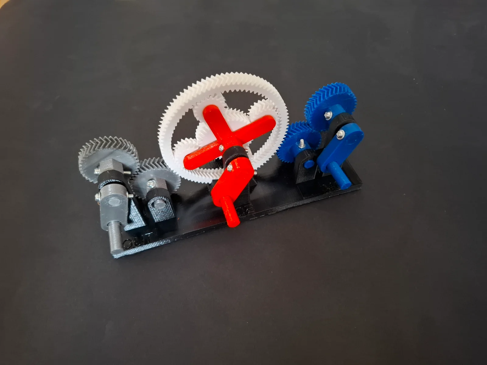
Simple model of the E-CVT used by Toyota and Ford in their vehicles, for example the Toyota Prius and Ford Maverick. This transmission uses a planetary gear set combined with electric motors to achieve an infinite amount of gear ratios within a given range. That means there are no belts that can wear out like in a normal CVT.
Internal combustion engines (ICE) are generally most efficient in only a small RPM range, normally around 2000 RPM. To keep engines in the optimal RPM range we use gearboxes, but normal gearboxes only have 5 to 8 gears, which limits the ability to get maximum efficiency at any speed.
This is where continuously variable transmission come in to take the efficiency crown. They have an infinite number of gear ratios (within some range), that allow them to keep the engine running at peak efficiency at all times. The main downside of a normal CVT is that it works by basically squeezing together a belt, which is as unreliable as it sounds. The E-CVT does not rely on belts, but instead uses a planetary gearset, two electric motor-generators and some cleverness to achieve optimal efficiency.
The setup of the E-CVT is as follows:
The ICE (Red) is connected to the carrier of the planetary gears
A small motor-generator (MG1) (white / green) is connected to the sun gear
A bigger motor generator (MG2) (blue) is connected to the ring gear, which is also directly connected to the output wheels (yellow / silver).
The main trick of the E-CVT is that the motor-generators can be used to convert power from the sun gear to the ring gear and vice versa using electricity. This allows them to convert the ICE's excess torque or speed to keep it at the desired RPM at all times.
Given the three inputs, there are 8 different modes, listed below. Try to replicate them all!
Modes
MG1
MG2
ICE
Wheels
Low load, low speed
Free
Clockwise
Held
Output
Engine start
Counter clockwise
Held
Output
Held
Normal drive
Output
Clockwise
Clockwise
Output
High load drive
Output
Clockwise (faster)
Clockwise
Output
High speed, low load
Clockwise
Output
Clockwise
Output
Coasting and regenerative breaking
Free
Output
Held
Slowing down
Reverse gear
Free
Counter clockwise
Held
Output
I recommend printing the model in five different colours: The base, the output and one for each input. For convenience the components of each color are on their own plate in the 3mf file. PETG is recommended over PLA for its better heat resistance.
Important slicer settings:
At least 3 walls, 15% infill
Random seam placement
Supports are only needed for the planetary gear carrier
You need to print the following parts, which I highly recommend color coding for clarity:
base (black)
planetary_gear (printed in place) (white)
MG2 shaft (white / green):
sun_shaft
shaft_handle
ICE shaft (red):
carrier
planet_shaft
shaft_handle
MG1 gears (blue):
small_shaft
small_gear_reverse
small_shaft_h
small_gear
shaft_handle
Output gears (silver):
small_shaft
small_gear_reverse
small_shaft_h
small_gear
shaft_handle
You need:
10 16-20mm M3 screws
10 M3 nuts
10 M3 washers
(Optional) 10-17mm Rubber feet for the base
Assembly is fairly simple. First, start by putting the carrier into the planetary gears. Then the planetary gearset and carrier can be mounted onto their shafts and the base. They are secured to the shafts with through-hole screws and an embedded nut. Make sure the carrier is mounted relative to the base at the side of the ICE.
For the other gears, first place them approximately where they need to be such that they mesh with another gear, then add the shaft and secure the gear to the shaft.
The OpenSCAD source code and latest models are available on my Github page: https://github.com/Bob-vdV/ecvt-transmission.
This model is heavily inspired by Consulab's hybrid planetary gearset trainer. Check out their model on their website if you want a more robust version: https://www.consulab.com/products#cat_l3-hybrid-electric-vehicle_prod_em-200-29-053137-hybrid-planetary-gearset-trainer .
Now it might take some time to wrap your head around this thing, so I recommend watching one of the two videos below (not by me) that explain the E-CVT in more detail (using the Consulab trainer).
If you have any feedback on the design or something is unclear, please let me know!
ByMaxTheSpyLikes57Downloads528

 ByRobertoGalloc_356815Likes549Downloads1.8K

 ByWolf_115355Likes513Downloads8.4K

 ByZED4EverLikes313Downloads5.2K

 ByfifindrLikes500Downloads4K

 ByVC_DesignLikes679Downloads3.6K

 ByDan Schwartz SchwartzLikes744Downloads3.4K

 ByJordanK_858807Likes42Downloads430

 ByMAFIXMAFIX_337316Likes130Downloads379

 ByUpcrid3D_1585693Likes808Downloads2.1K

 ByWilko_SLOLikes935Downloads2K

 Bystephenhiras_1439037Likes15Downloads233