



Kẹp giữ sợi Filament
 Bytinx_1344834Likes1.2KDownloads6K
Remix of Mô hình CAD Lắp Ráp Giường Máy In Creality K1 By Henlor
Build another version of this model.
I re-adjusted some parameters on my own while also using some of Henlor's parameters. For bed rigidity, it ONLY has to be unibody until I find the solution to get it done.
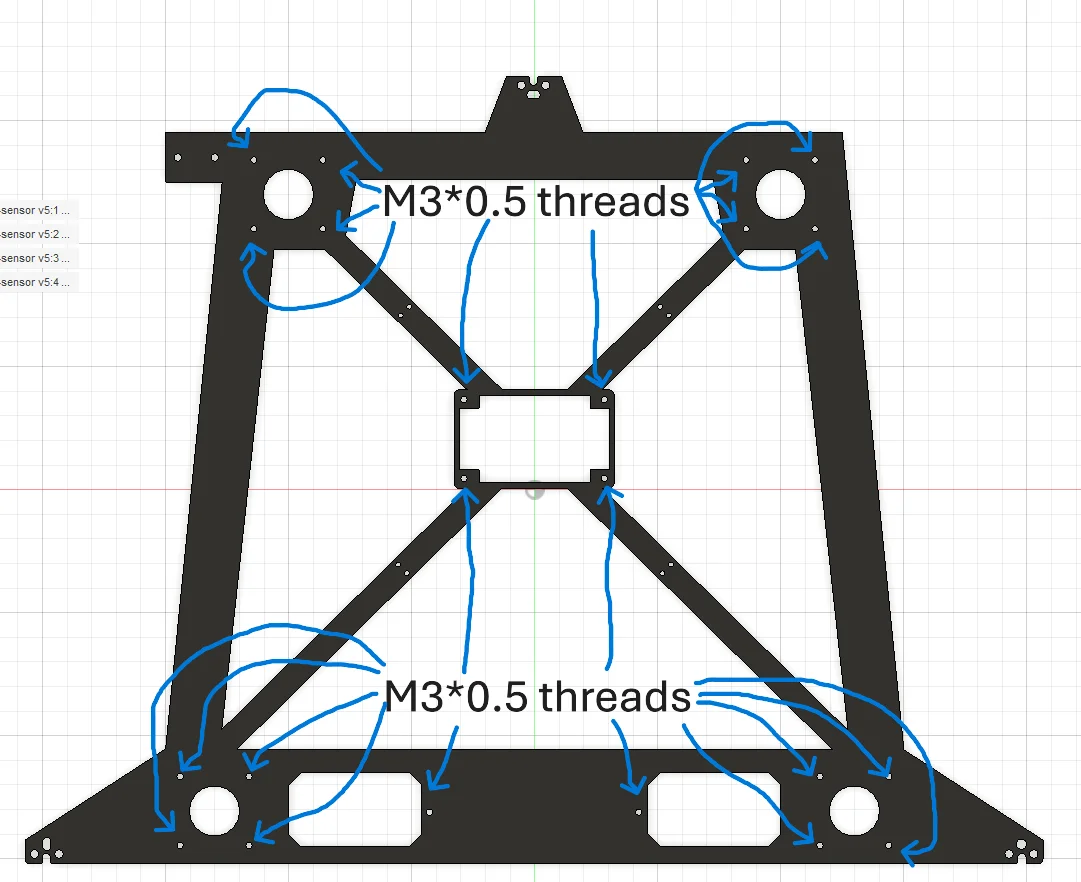
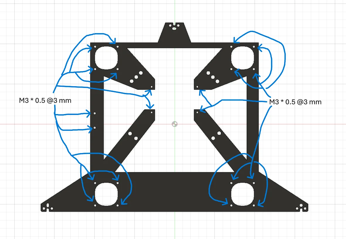
You can take the drawing file with the places to tap the threads for such CNC services like PCBWay/JLCCNC. I also found sheet metal cheaper than CNCs, so try them if possible.
You can still use the stock accessories, but here's the link for the adjustable carriages as well as the side-mounted 4010 mounts, front-mounted 5015 fan mounts, and their MAX version. You can also use a side-mounted 5015 mount as well. For the Triple Z upgrade, DO NOT use the adjustable carriages. You'd better use an Oldham connector instead.
Measured with only my tape measure for the large areas. May not be accurate. If you found it inaccurate, tell me it's inaccurate in the comments. I want to, have to, and can't wait to hear from you. I'll also test this model to get the process faster.
Major thanks to Henlor for building the tough foundation for this experiment project. Take a look at what he did for the Creality K1.
[K1 Max] With this carriage, it no longer supports the LiDAR sensor. Calibrate the filament on OrcaSlicer instead. They work really well.
I also provided the STEP file, so feel free to add your own fixes. I appreciate your work. When using without the load cells, you can fix the bed with four solid mounts.
If you choose to use this mount, while still possible to use the stock mainboard, I heavily recommend you to swap the mainboard, just like how I did this with my Manta M5P.
[67 % - Hotfix 11/11/2025] Now RGB sticks and loadcell PCBs share the same spacers. Print at least 10 of them.
Coming soon.
[Done 10/19/2025] Stock load cells - with a spacer for safety measures.
[Done 10/19/2025] RGB LED mount to replicate the progress LED on H2S - because I was a little envy of it ;)
[Research in progress] Heat inserts or nuts instead of tapping.
[Research in progress] Custom bed for less weight.
[67 %, work in progress] For the K1 - Added STEP.
Scrapped ideas
[Scrapped 11/20/2025] Multiple smaller pieces to make it printable.
Prepare.
Make sure you have all the parts to use.
1 bed frame
4 bed mounts(or load cells)
10 nylon cable ties
4 bed spacers
4 PRTouch PCB spacers
30 M3*6 (mm) BHCS screws
10 M3*8/10 BHCS/SHCS screws
4 M4*25/30 FHCS screws (or original screws @20 mm) (=bed screws)
1 RGB LED stick (I designed it for this one)
2 LED spacers
Home all axes. (for the last time.) G28
Move Z to bottom. G0 Z200
Unscrew the bed.
Take the nuts out of the printer, but keep them safe.
TURN THE PRINTER OFF. (just like that tv.)
Detach.
Put the bed to the side of the printer.
New beds: Unplug the bed cable. It's connected to a part called SSR next to a power supply. Multiple cables in a nylon sleeve - these are the wires you detach from the SSR.
Especially for the board-swapped K1s, you would either ditch the stock SSR or reuse it. Wire the bed cables accordingly to the manual in any cases. Wiring like what the manual says is the best wiring.
Unplug every cable on PRTouch PCB.
Detach 4 load cells and their main PCB.
Undo 2 screws on each carriage. It should undo 6 screws.
Move to step “Assemble.”
Assemble.
Below this are for those who want to use the load cells.
Take the bed frame and install the load cells and their main PCB.
The PRTouch PCB should be installed like this:
Connect the load cells to the main PCB.
Install the load cells with 4 M3*6 BHCS screws for each one.
Tie each cable with cable ties, using provided slots.
Below this are to install the bed. (New beds can be installed this way as well.)
Assemble the bed first, following their manuals.
Take 4 bed spacers and put it onto each load cell(or bed mount).
With the bed base face up, put 4 M4 bed screws into each hole.
Quit this section for a while and move to step 3 in “Remount” until the manual says to move to this step.
Put the nuts on the screws and tighten them ONLY BY HAND.
Tie the bed cable with cable ties. You can use two holes on the back left side of the frame.
If you want to use the factory bed, install the bed when the frame is mounted.
Install the RGB LED here, just like this:
Remount.
Screw the new bed frame to each carriage with 6 M3*8 screws.
For the factory bed, move to step 2 of bed installation on “Assemble.”
If you decided to keep using the stock load cells, plug the PRTouch PCB cable back in.
Go straight back to step 5 of bed installation on “Assemble.”
Once everything is connected, you successfully completed the installation.
Calibrate.
Once done, home all axes. G28
Move Z to 300. G0 Z300
G0 Z250Turn off steppers. M84
If needed, using the tooth skip method, bring the Z frame as down as possible.
Home all axes again. G28
Calibrate the bed till it's flat.
DONE! Print a test model and inspect it.
Happy printing!
Bytinx_1344834Likes1.2KDownloads6K

 Byprusa-researchLikes0Downloads2.7K

 Bydet-manLikes0Downloads176

 Bygummiegecko8477Likes0Downloads168

 BydalleLikes0Downloads150

 BynasikLikes0Downloads121

 Byarhi_585078Likes64Downloads546

 ByHanzo3dLikes155Downloads417

 BydarienLikes0Downloads1K

 ByGeek5DLikes147Downloads490

 ByBrokentooth_designsLikes23Downloads412

 Byla-cave-au-chatLikes0Downloads972