



Còi Tàu Hơi Nước Mini
 ByfifindrLikes500Downloads4K
Build another version of this model.
 Fractal Vise cho bàn xoay Revopoint Dual AxisByKentacles_535229 · 04/16/2026
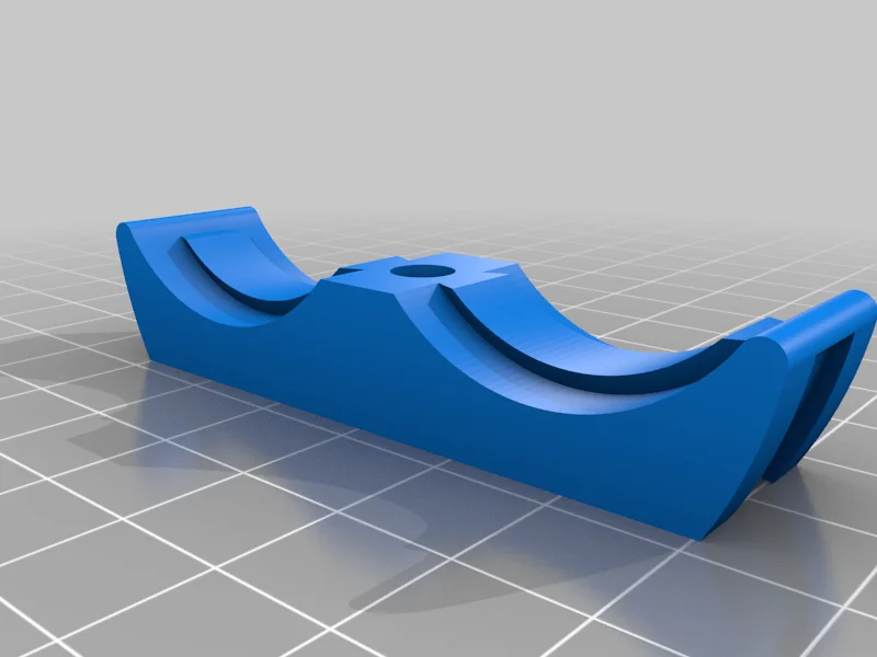
 Thân Giữa Của Kẹp Fractal Cho Đai Ốc Loại Đối Xứng TrụByPaparazzi_17575 · 04/08/2025
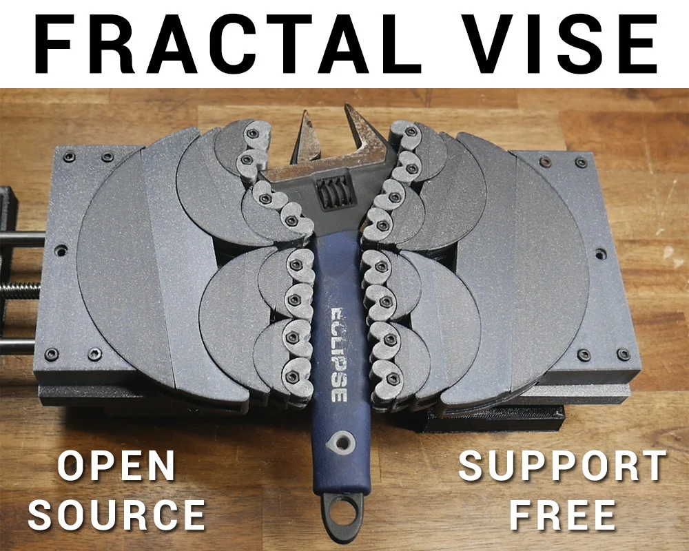
A 3D printed fractal vise inspired by the original seen on a Hand Tool Rescue video: https://www.youtube.com/watch?v=QBeOgGt_oWU
I wanted to make my own version that was:
It works! https://youtu.be/99Qh1oR2A6A
See all the details and how to assemble in this video: https://youtu.be/eCfw9fd0mHg
John Toebes has created an assembly of the vise with proper constraints and that means you can virtually animate it: https://cad.onshape.com/documents/a04375fc5dd6de20b79fc182/w/2a6a78f95915396eb3ffce36/e/630372eae2ff8acb648f5026
More details below.
Printer:
Rat Rig V-core 3
Rafts:
No
Supports:
No
Resolution:
120
Infill:
30
Filament:
X3D PLA
Diamond silver
Notes:
All parts corrected orientated for printing without support.
0.12 mm layer height or similar layer for any parts that have a dovetail joint.
0.2 mm layer height for the remaining parts.
TPU for the feet, PLA or whatever you like for the rest.
It is vital that the bottom of the parts are flat and without any elephant's foot.
I recommend printing test parts such as B2 and C1 to make sure of fitment for printing the rest.
Printing BOM:
D half: 32 in total (2 per finger, 16 sets)
C1 and C2: 8 of each
B1 and B2: 4 of each
A1 and A2: 2 of each
holder: 2
collar: 2
end body and cap: 2 of each
middle body and cap: 1 of each
foot: 2
handle and handle clamp: 1 of each
spacerA and spacer B: 2 of each
Required hardware
8mm lead screw and nut x 1 + 8mm round rod x 2. Leadscrew should be at least 50 mm longer than rods. I used 315 and 365 mm.
LM8UU bearings x 4 (8 mm ID, 15 mm OD, 24 mm length)
608 bearings x 4 (8 mm ID, 22 mm OD, 7 mm thick)
D halves: 1 M3 nut + 1 M3x12 mm bolt (each, 16 sets in total)
C1 to C2: 1 M3 nut + 1 M3 x 10 mm bolt, two short lengths of 1.75 mm filament (each, 8 sets in total)
B1 to B2: 1 M3 nut + 1 M3 x 20 mm bolt, two short lengths of 1.75 mm filament (each, 4 sets in total)
D1 to D2: 2 M3 nuts + 2 M3 x 35 mm bolts (each, 2 sets in total)
holder to spacerA/B: 8 M3 nuts + 8 M3 x 20 mm bolts (total)
spacerA/B to end/middle body: 8 M3 nuts + 8 M3 x 20 mm bolts (total)
end body to end cap: 32 M3 nuts + 32 M3 x 20 mm bolts (total)
Middle body to middle cap: 16 M3 nuts + 16 M3 x 20 mm bolts (total)
Collars: 2 M3 nuts + 2 M3 x 14 mm bolts (12mm works but is is very tight and 16mm works will protrude) (total)
Handle clamp to leadscrew: 2 M3 nuts + 2 M3 x 14 mm bolts (12mm works but is is very tight and 16mm works will protrude)
Handle clamp to handle: 1 M3 lock nut + 1 M3 x 20 mm bolt (longer is ok but will protrude)
Category: Hand Tools
ByfifindrLikes500Downloads4K

 ByVC_DesignLikes679Downloads3.6K

 ByDan Schwartz SchwartzLikes744Downloads3.4K

 ByZED4EverLikes313Downloads5.2K

 Bychubbs8697_2027893Likes585Downloads1.7K

 Byquibeck_3353173Likes965Downloads1.9K

 ByRungeKuttaLikes229Downloads1.2K

 ByEadubsLikes228Downloads1.3K

 ByJeremyVillalo_760366Likes68Downloads767

 Bykjus_448782Likes314Downloads673

 ByBS_PB_4005052Likes48Downloads142

 BySchmitzBertLikes95Downloads629