



Còi Tàu Hơi Nước Mini
 ByfifindrLikes500Downloads4K
Remix of Móc treo cáp âm tường chắc chắn By itguru
Build another version of this model.
 Móc treo cáp 3D siêu bền - Thiết kế nhỏ gọn, tối ưu không gianByMrExo3D · 05/03/2026
 Móc treo tường cho ba lô (Backpack Wall Hook)Bynvrprfct_916343 · 04/29/2026
 Móc Treo Dây Điện (Cứng Hơn) Gắn Cây GỗByA4O_Labs · 12/03/2025
 Móc treo Hookzilla cho nhu cầu treo cực lớnByAdamL · 12/03/2025
The parent design is good, but I wondered, could I use about the same amount of material, but make it stronger/better? The answer, thanks to Fusion360's generative design inspiration and stress analysis is yes!
I hope this improved design helps people hold just a little more weight with the same amount of plastic!
Provided in 3MF & STEP formats to make people's lives easier.
Recommend printing in 4+ perimeters in PETG, ABS/ASA or PC. PLA might be a problem because while it is stiff and strong, it has an undesirable tendency to creep over time.
The change here is very simple, although a little counter-intuitive. By reversing one of the support struts, the total static load bearing capacity of the hook can be significantly improved, as shown by simulation. I got the idea to do this redesign the strut this way from looking at some generative design ideas Fusion360 generated when I looked at the best way to support weight on this hook design and it kept showing me the reverse strut direction under the hook curve, like this:
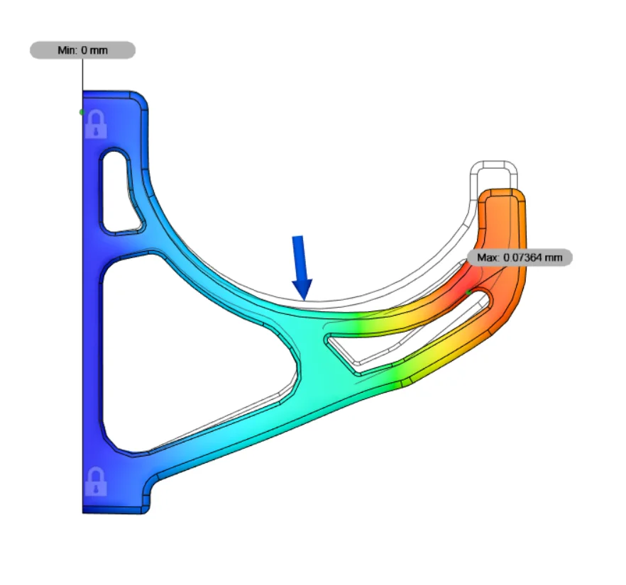
After I modeled both of them, the strain analysis shows the improvement to be significant for essentially the same amount of filament used (more or less, designs are not exactly equal).
Simulation of an 85 N load at 10 degrees (~19 lb of weight on a 100% solid simulated part) shows ~½ as much displacement in this new design versus the old design, demonstrating the superior stiffness and load bearing capacity. The relative safety factor is also increased from ~7.8 to 9.2 at this load. Comparative pictures below. Note that displacement is exaggerated here to visualize.
Old vs new:
ByfifindrLikes500Downloads4K

 ByVC_DesignLikes679Downloads3.6K

 ByDan Schwartz SchwartzLikes744Downloads3.4K

 Bychubbs8697_2027893Likes585Downloads1.7K

 Byquibeck_3353173Likes965Downloads1.9K

 ByRungeKuttaLikes229Downloads1.2K

 ByEadubsLikes228Downloads1.3K

 ByWolf_115355Likes513Downloads8.4K

 ByJeremyVillalo_760366Likes68Downloads760

 ByZED4EverLikes313Downloads5.2K

 Bykjus_448782Likes314Downloads671

 ByMatthew_GhostLikes350Downloads934