



Grippy Broom Holder
 Byvc-designLikes0Downloads3.2K
Build another version of this model.
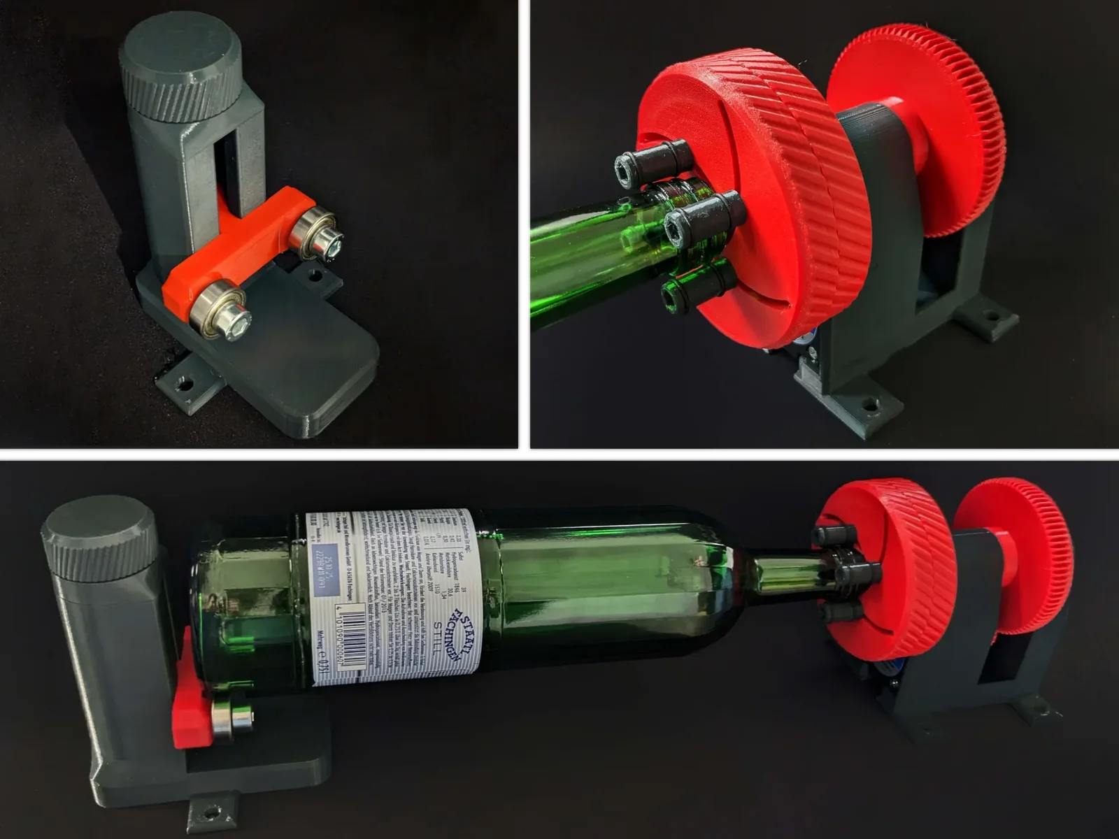
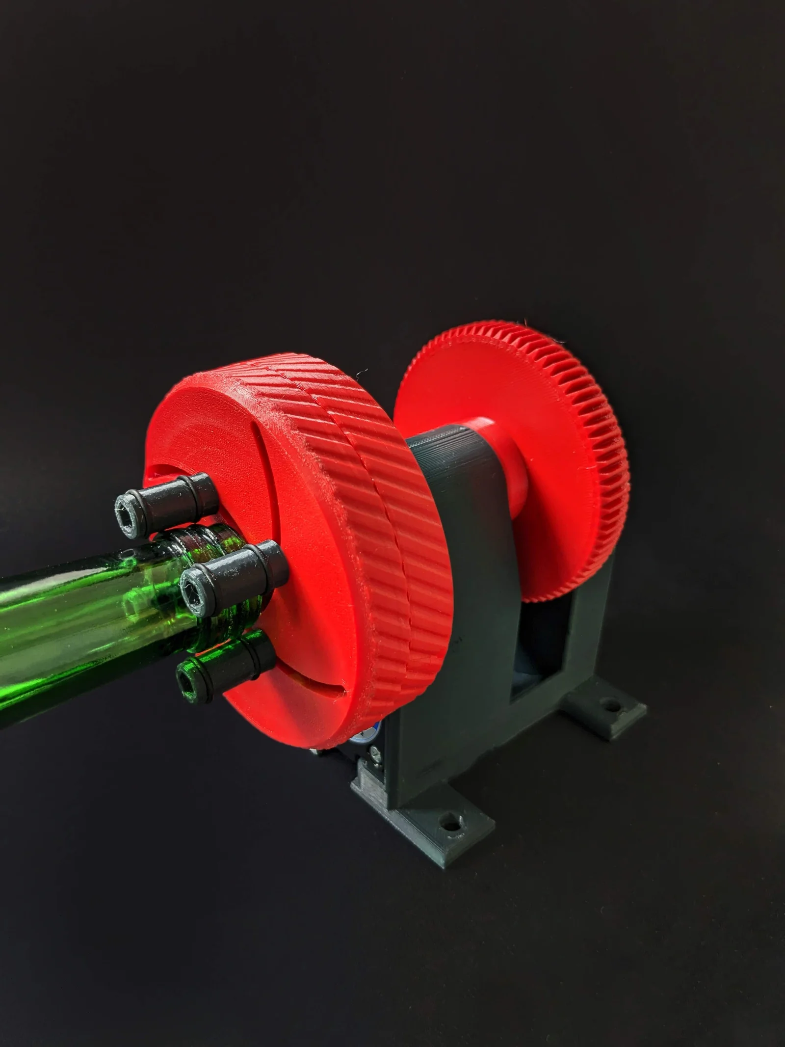
Round components can be lasered with this ratation system.
I made this model for a friend, it is based on the "Rotary Axis For Diode Laser" from "ThothLoki".
According to his own statement, the model contains some problems, therefore I have redesigned it from scratch.
Long bolts are needed, since they are often not available, it is easier to use a threaded rod and nuts.
If you hit with a center punch between the nut and threaded rod, they are securely joined together.
pc.
Name
Norm
Info
6x
bearing 608-ZZ
DIN 625-1
2RS is ok too
3x
M8 Self-locking nuts
DIN EN ISO 10511
5x
M8 nuts
DIN EN ISO 4032
1x
M8 125mm - Threaded rod
for counter support
1x
M8 (xxx mm) - Threaded rod
for chuck and engine mount
4x
M3 Self-locking nuts
inside the chuck jaws
3x
M3x30 socket head screw
ISO 4762
inside the chuck jaws and motor
3x
M3 Square nut
DIN 562
inside gears
3x
M3x10 socket head screw
ISO 4762
or set screw / inside gears
2x
M3 nut
for motor
3x
M3x15 socket head screw
ISO 4762
for counter support cover
2x
M8x22 socket head screw
ISO 4762
for counter support bearings
8x
8x1,5 o-ring
Since there are a lot of stepper motors with different dimensions, I created the assembly so that the dimensions on the engine mount adjust as soon as you change the stepper motor. The length of the screw also adapts.
After uploading to Fusion, you will see four files. When you open the Nema 17 stepper motor, you can edit it.
In Fusion there is a timeline at the bottom with all the features. By right clicking on it, you can edit it and enter the desired dimensions.
If you open the assembly rotary system, you will see a yellow exclamation mark in the upper left corner. After clicking on it, the assembly rebuilds itself and everything has the desired dimensions.
The STL file from the engine_mount-V3 is for a 48mm long 17HS19-2004S1.
In the case of short motors, it may be necessary to remove two diagonal screws so that the motor can be screwed into the holes that have become free.
The upper self-locking nut must be adjusted so that there is a small gap between the rotary knob and the cover.
Grease should also be applied to the thread.
The positioning arm should slide in the guide without much play. If it does not move easily, the surfaces can be filed down slightly. WD40 will make the surfaces shiny again.
Material: PETG
Infill: 30%
Perimeters: 4
Layer height: 0,15 mm
Support: no
Only the chuck-part-2 needs support at the edge, the screw hole in the middle is designed to work without support.
24.01.2024
An user wrote that the area for the cables is too tight. The clearance for these was therefore extended by 2 mm.
04.03.2023
Assembly completely updated.
11.01.2023
When testing the prototype, we noticed that a gear ratio of 1:1 is not optimal for this. Due to the 200 steps of the stepper motors, gaps appear at larger diameters of the laser part. Therefore, the gears were adapted to a ratio of 1:5.
Old:
Byvc-designLikes0Downloads3.2K

 BySeppoTakaloLikes960Downloads1.9K

 Byrb_200934Likes48Downloads1.1K

 ByZED4EverLikes313Downloads5.2K

 ByfifindrLikes500Downloads4K

 ByVC_DesignLikes679Downloads3.6K

 ByKNIN_CustomLikes112Downloads438

 ByDan Schwartz SchwartzLikes744Downloads3.4K

 ByUpcrid3D_1585693Likes808Downloads2.1K

 ByWilko_SLOLikes935Downloads2K

 Bychubbs8697_2027893Likes585Downloads1.7K

 Byquibeck_3353173Likes965Downloads1.9K