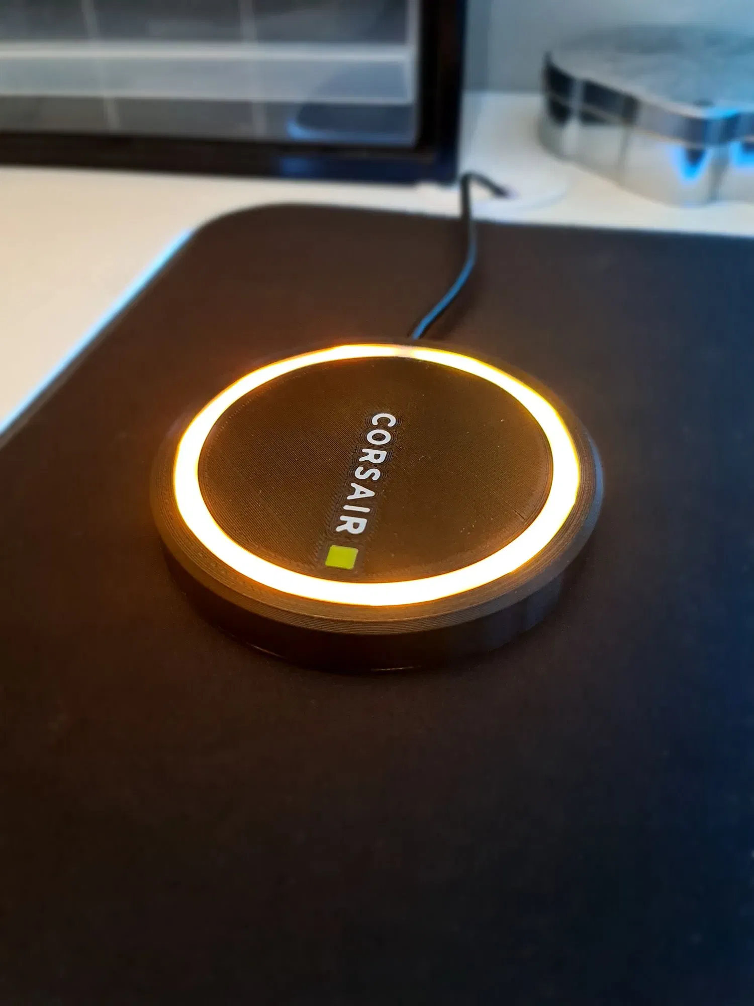
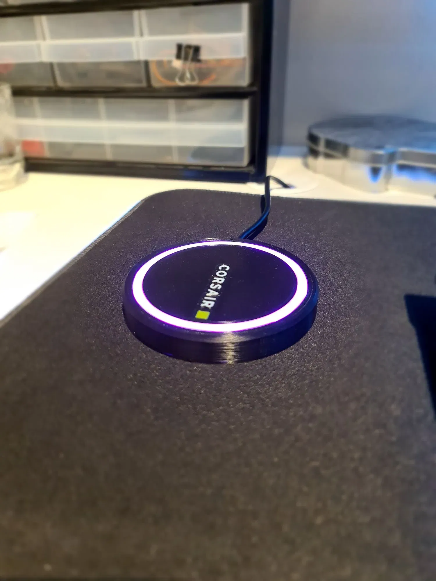
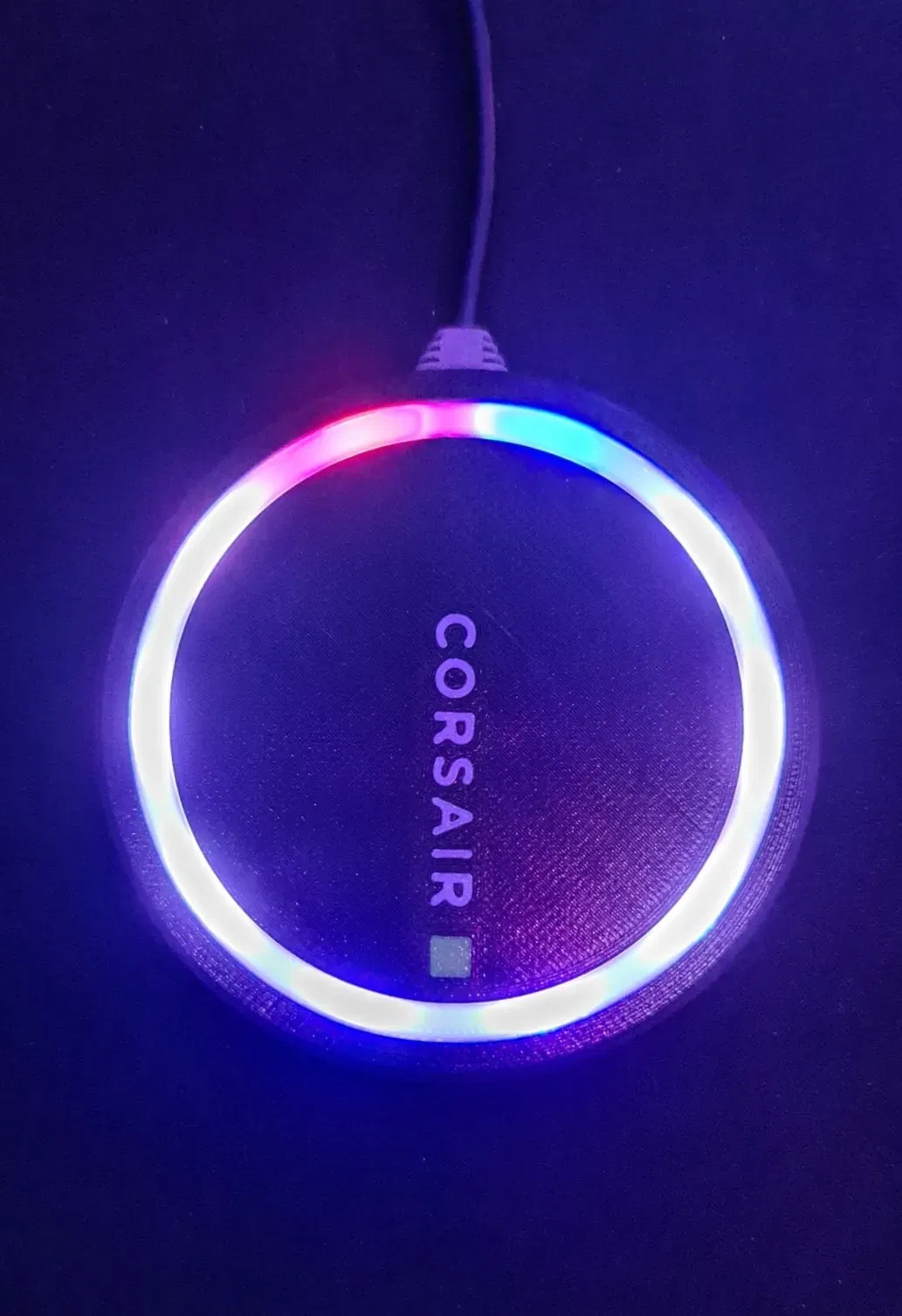
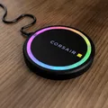
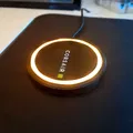
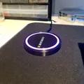
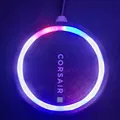
Corsair RGB Coaster

Đây là một tàu lượn USB, RGB sử dụng nút chiếu sáng Corsair và dải LED. Vui lòng đọc hướng dẫn đầu tiên!
Mô tả
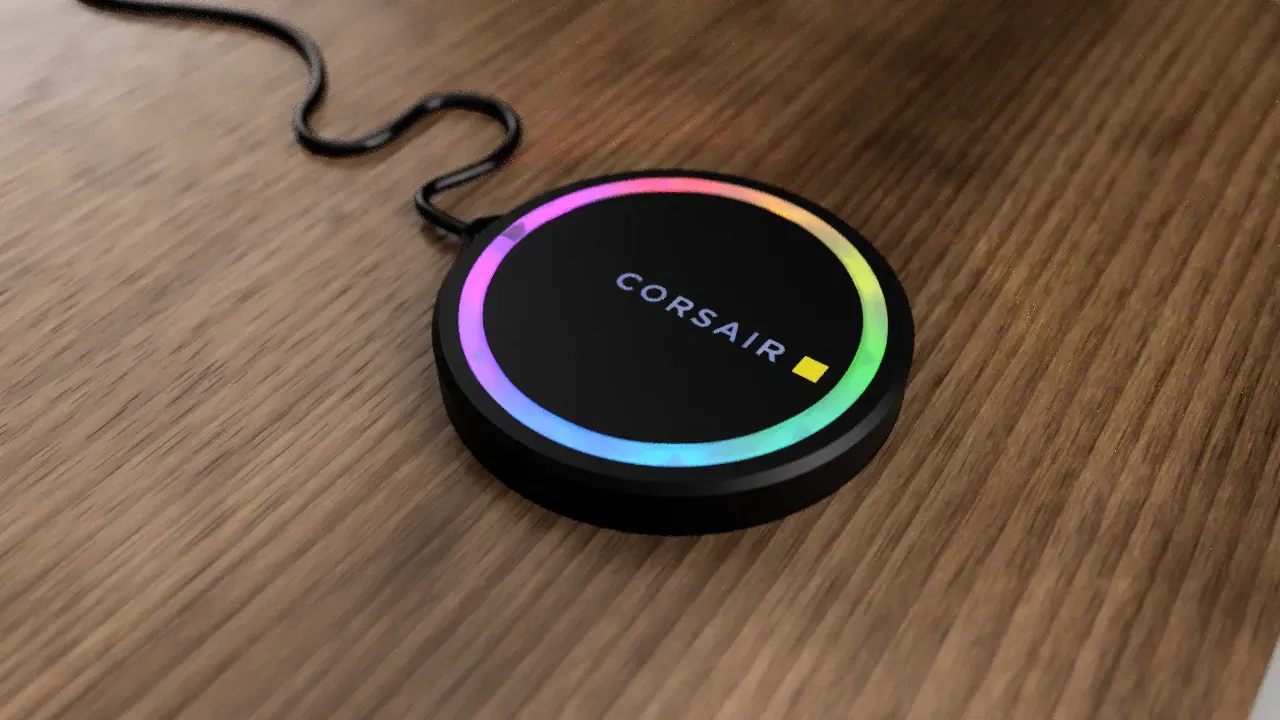
Corsair RGB Tea Coaster
Please read through all of the instructions, this is an advanced build and requires tools and knowledge on basic electronics, soldering and of course, 3D printing. All parts are designed to be printed without supports but require some advanced printing techniques detailed below.
Parts List:
1 x Lighting Node Pro Hub 1 x Corsair LED Strip 3 x M3 X 6mm Bolts (3mm bolt width, 6mm length) 3 x M3 Threaded Heat Insert (4mm OD, 3mm ID, 4 – 6mm Length) ** 3 x M2.5 x 3mm Bolts (2.5mm bolt width, 3mm Length) ** 3 x M2.5 Threaded Heat Insert (3.2mm OD, 2.5mm ID, Max 3mm Length) PLA or PETG in White, Yellow and Black (PETG for better heat resistance but I have been testing with PLA without issue) TPU in black for the strain relief
** if using M2.5 bolts here, you will have to carefully drill out the holes on the lighting node pro as they are slightly smaller than an M2.5 bolt. If you would prefer, you can use M2 (2mm OD) bolts and threaded inserts instead.
Equipment Required:
3D Printer Soldering Iron Wire Cutters Screwdriver appropriate for the bolts you use Hobby Knife/Scalpel and blades Multimeter
Multi Colour Parts Printing Process:
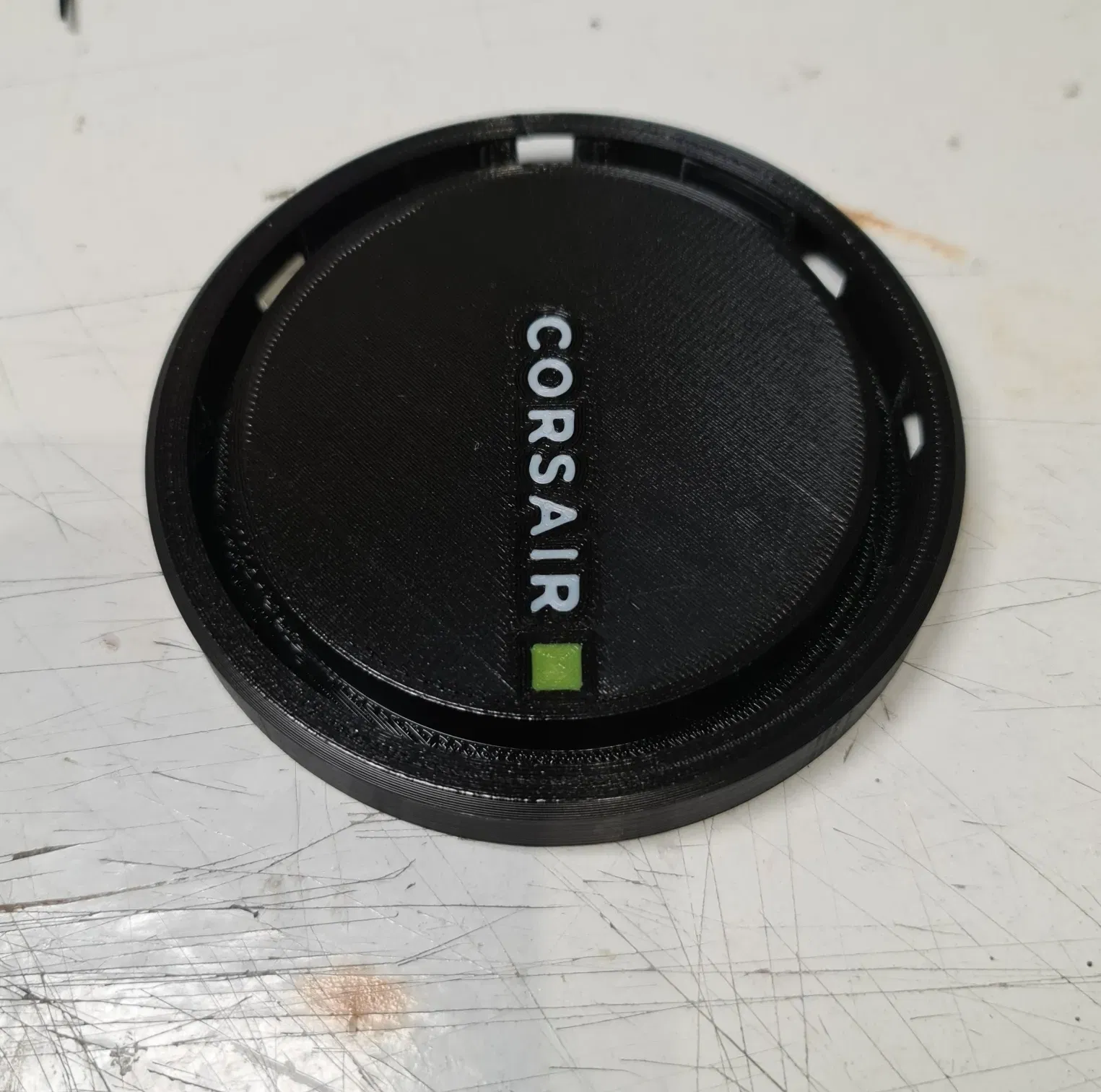
Open the file ‘Coaster Top’ in eSlicer and when prompted tell it to import the models so your printer settings are not changed. You will need to delete all the models apart from the ‘corsair’ word for now – you can do this in the Object List on the lower left of the screen. Print this in white with no brim or skirt. You just want the logo left when done. This first layer should be 0.3mm layer height but after that I went to 0.2mm for a nicer finish - you can use any layer height you wish as long as the first layer is 0.3mm. leave eSlicer open for now.
Stay with the printer because as soon as it is finished you will need to tell it to preheat the bed to prevent the parts from coming loose.
Between prints remember to remove any purge line from the bed before starting the next print.
Go back to Cure and you should be able to undo (Ctrl + Z or Command + Z) the delete to bring everything back (Alternatively you could re-open the project again). This time you want to remove everything but the square for the logo. This should be printed in yellow with z-hop now enabled, I used 0.3mm hop. Again, no brim or skirt, just the logo. Leave eSlicer open once again.
If done correctly you should have a nice-looking logo on your bed in two colours with no other material. Back in eSlicer, undo the delete process and now remove everything but the base itself. This should be printed with z-hop of 0.3mm again to avoid it bumping into any printed parts on the bed. The first layer is at 0.3mm and subsequent layers can be 0.2mm for a finer finish.
This is the method I used to print multi colour parts and the same process is repeated later for the ‘combined lower base project’ file. This time the logo parts are printed in white or light grey (but really whatever you want, and you could even leave the actual logo out if you wish as the gaps can be bridged easily to leave a recess).
All Other Parts:
Here is a list of the proposed colours and materials that should be used for the rest of the parts along with the number of each you will need. The details about the colours for the first two are detailed above.
| Part Name | Colour | Material | Quantity |
|---|---|---|---|
| Combined Top | Black, White, Yellow | PLA/PETG | 1 |
| Combined Base | Black, Grey/White | PLA/PETG | 1 |
| Diffusion Ring | White | PLA/PETG | 1 |
| Strain Relief | Black | TPU | 1 |
All the files have been saved as projects with parts in the correct orientation and quantity already but you can change this if you need to for some reason. Parts are all designed to print without support material and with the surface you will see on the outside touching the bed for best surface quality.
Printing Notes:
When printing the main base and lower base, try to make sure the z-seam is placed at the back where the strain relief goes to stop it leaving an ugly seam at the front. Printing slower with smaller layer heights will yield much better results but the first layer must be 0.3mm to account for the height of the layers of the logo.
The lower base has a sacrificial layer which allows the raised bolt holes to be printed without support. This will create a single 0.2mm layer where there should be a 3.5mm hole. You will need to use a fine bladed tool to remove this, I used a hobby knife with a number 10a blade.
I printed the white diffusion ring with no infill, 2 walls and 3 top and bottom layers however different brands and materials will have different opacity and will require a bit of testing to find the right settings to allow light to pass through.
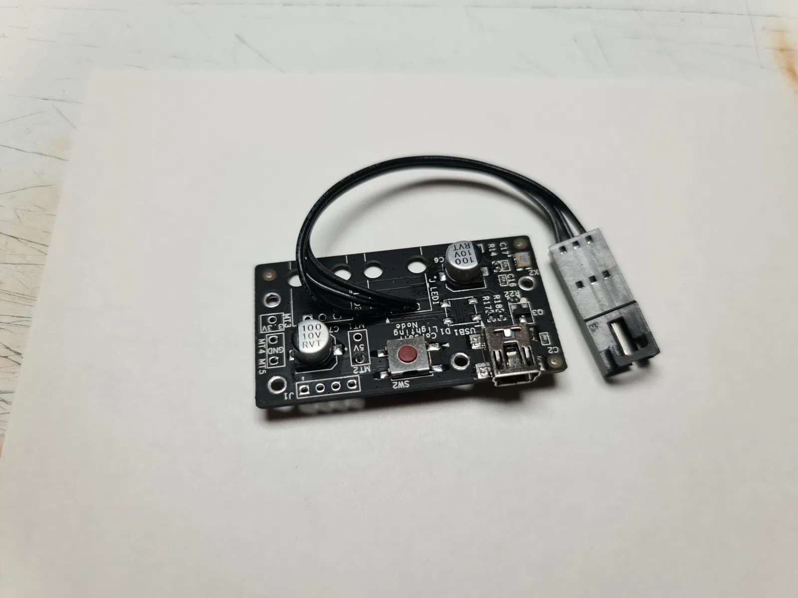
Node Pro:
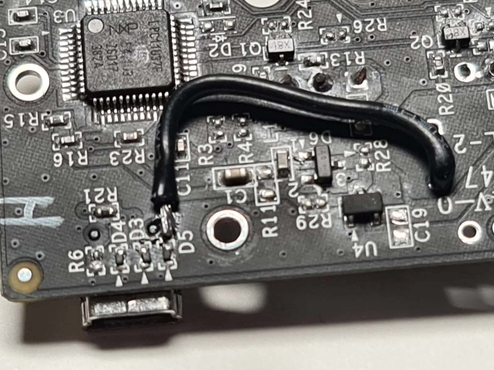
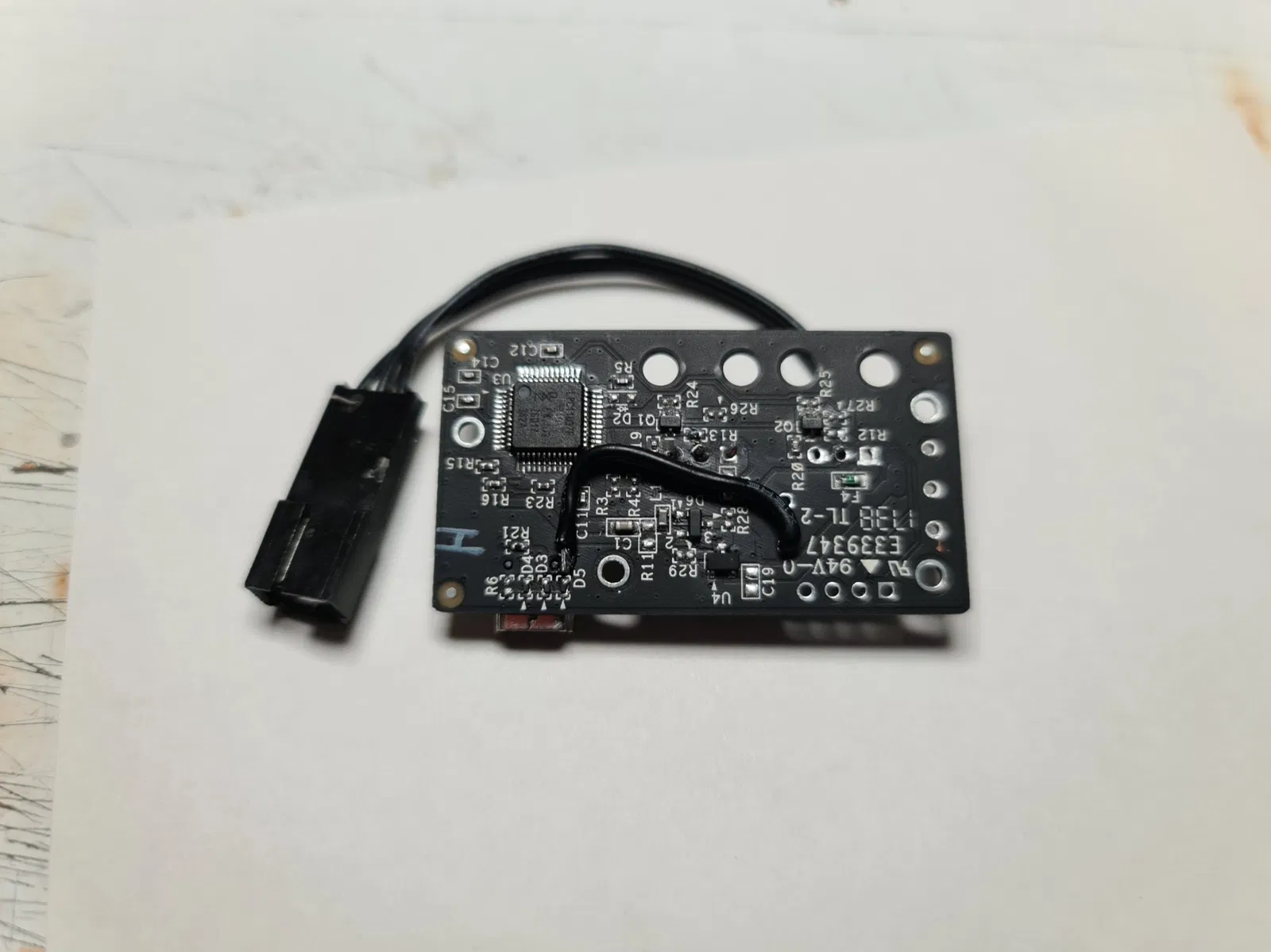
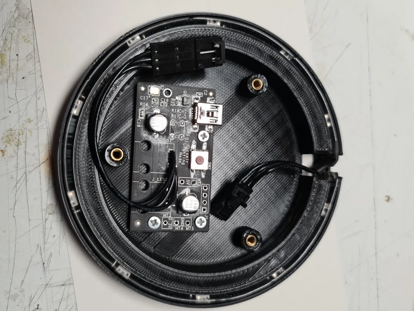
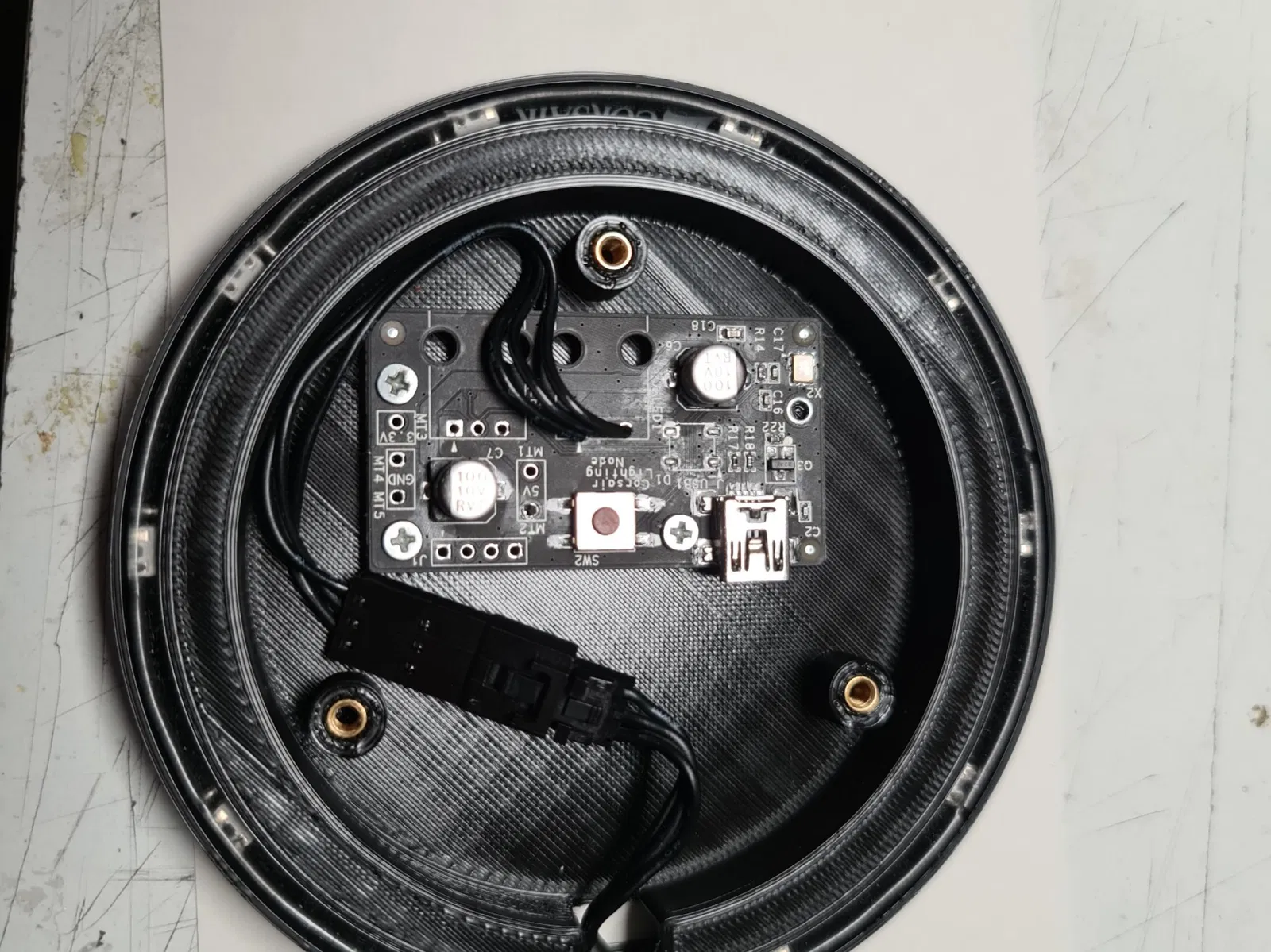
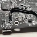
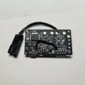
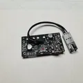
If you are using a node pro in the way that I have, you will need to make some modifications. First remove the casing and then the two ports for the LED strips. You will also want to remove the SATA power cable. I replaced one of the ports with a cable extension so I could plug the strip in, but you can solder the strip in place in you want - just make sure it is connected in the same way the original plug for the strip was connected. You will need to check the board with a multi meter to see where the 5v supply comes from the USB. I found this on the back of one of the diodes next to the USB port. This needs to be botched to the 5v supply on the strip so that the strip can be powered by the USB port instead of the SATA power cable.
Look at the included pictures to see what I did with the Lighting Node Pro but you will need some electronics knowledge and equipment to do this properly.
As the power cable has now been removed, this strip is powered directly from the USB port, so you will want to plug it in directly to the motherboard, preferably in a USB 3 or above port. This has worked for me perfectly fine for over a year now, but your milage may vary.
Construction:
The construction is simple once you have modified your node pro. The most difficult part is to get the usb cable connected and this will depend on the type of cable you are using. I managed to get a standard cable to fit with some bruit force, but a 90-degree connector might work better.
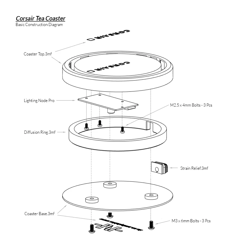
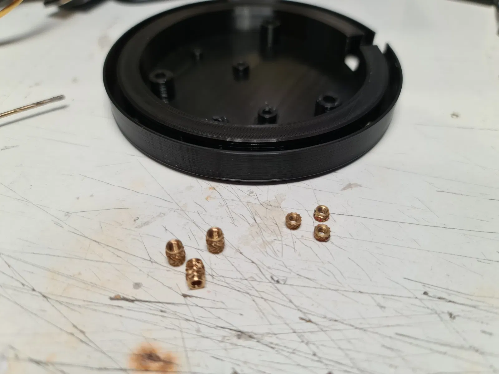
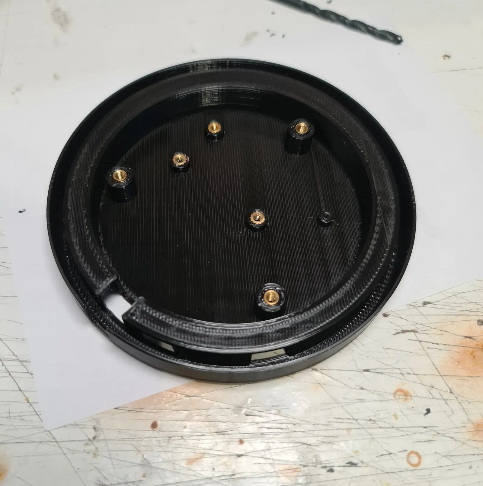
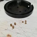
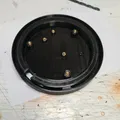
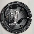
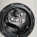
You will need to start by using a soldering iron to insert the threaded inserts into the base. Look at the images to see which ones go where, the smaller M2.5 inserts are for the node pro and the M3 inserts are for the base of the coaster to attach to the main body and close the coaster up.
The LEDs will need to have the connector removed from one end of the cable (inside the light ring) and the other end can be clipped to be soldered to the board directly or you can add a connector to the board which is what I did (see pictures for a better idea of my layout).
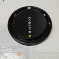
Once everything is prepped you can add the LED strip into the void in the bottom of Coaster Top.3mf. Make sure the LEDs are aligned with the holes into the centre where the diffusion ring goes. The two ends of the strip should meet each other in the gap at the back of the coaster.
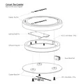
The construction diagram will show the orientation of the parts and the images will give you a better idea of the arrangement of everything.
Disclaimer:
This will void the warranty of the Node Pro and may damage it permanently if done incorrectly – and perhaps even if done correctly. Using the Node Pro on a USB 1 or 2 port may damage the port if too much power is pulled by the Node Pro, so I recommend using a USB 3 port. This project is undertaken at your own risk and any damages to equipment, people, animals, or the environment as a result is your own responsibility and I accept no liability for these damages.
Have fun and if you have any questions, let me know!
Giấy phép

File mô hình


Chưa có bản in nào được khoe. Hãy là người đầu tiên!

Chưa có bình luận nào. Hãy là người đầu tiên!