



Ốp lưng cho Samsung S22 Ultra
 ByckthLikes148Downloads2.4K
Build another version of this model.
Note: I am currently working on a much better V2 of this model, it will hopefully be done in a few months.
Update 2025-08/05 - Added my Mobiflight preset and a section in the end explaining it.
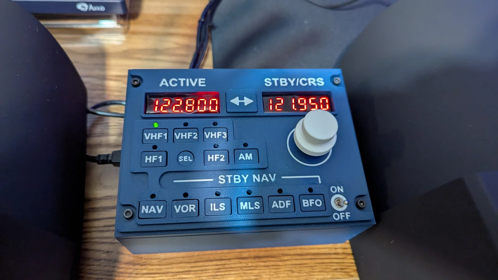
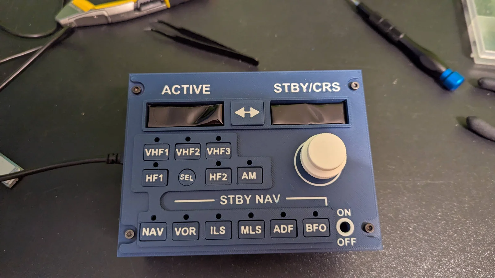
This is a 3d printable radio management panel for the airbus A320. I tried making it as accurate as the real one, and to my knowledge it's the same width as the real one. But I wasn't able to fit all the elctronics in the right height (mainly the seven segment displays) and had to make it taller than the real one. And I'm still quite unsure what the real size of the RMP is since the more reaserch I do the more dimensions i find 😊.
In it's current version the RMP doesn't include any backlightning (except for the button LEDs) but this can probably be added very easily for the panel (not sure sbout the buttons though).
Right now it is 148mm wide and 111mm tall and a thickness of 10mm from top to bottom.
Since I wanted it to have multiple colors the print files might look a bit messy. But the first step is to choose whether you want to print in multiple colors or in one color. The single color has a 1mm “hole” in every letter and line.
Multi Color
To print in multicolor start with example the buttons, download all the OBJ files for the buttons and the .mlt files under the “other files” tab. I recommend placing both the OBJ files and mlt files in a new folder, but as long as they're in the same folder and have the same name it should be fine. Like this:
OrcaSlicer/BambuStudio/PrusaSlicer
I have only tested this in Orca and Bambu, but since they are ell based on prusa I'm guessing it works kind of the same ;). Start by adding another filament (1) and changing the AMS slot to the correct one (2). Import the obj file and a dialog will popup where you can map the model colors to a filament (3). For the white model color select the blue filament color (or another) and for the red model color select the white filament color.
Once you've imported two additional nonexistent filaments will appear which you can just delete (the button next to the (1) button, spool with a minus). Then orient face down, slice, and print!
Cura
I'm not sure how multicolor printing works in Cura but it's probably a similar procedure.
Print Settings:
Nozzle: 0.4mm
Layer Height: 0.2mm
Infill: 15%
Most parts manage without supports but not all.
14 pcs 6mm tactile switch, I recommend buying a set and choosing preferred height: https://www.amazon.com/TWTADE-Momentary-Assortment-Latching-QC-6X6MM/dp/B0858XRGYW/ref=sr_1_1?crid=30ASUUG4AK1NL&dib=eyJ2IjoiMSJ9.azHG1rngTTewVls4x4IzR25T-19IjVUAqfy5aoaP7cfO0ggLmwBxWmyFUdudLhwGH7iK3ceMdLNC6sdo2_hY4hsZdXLRleXV5pgc5_la0YkaLCkJ0Lzs0UZyWeKi4QCpXqIwPfr1U7uMNEIG-Y6-h2IZnyblpkp4_sIgZcjNukGGau5afvLOQp9ToPhOT6uZxFh2gAS3PIINy2gMSxTfUih6Mx1M6okpfQQu00Ip9zI.enUux92zh0960eUxA1WJoB6YXQuXJY9kdqK8Tj8GzJg&dib_tag=se&keywords=6mm+tactile+switch&qid=1742636498&sprefix=6mm+tactile+switch%2Caps%2C174&sr=8-1
2 pcs TM1637 0.36 inch red 6 digit with decimals seven segment display: https://www.aliexpress.com/item/1005002883995270.html?spm=a2g0o.order_list.order_list_main.165.52641802eMRrKc
12 pcs 3mm green LED diode: https://www.aliexpress.com/item/1005004543292837.html?spm=a2g0o.order_list.order_list_main.150.52641802eMRrKc
Arduino Mega 2560: https://store.arduino.cc/en-se/products/arduino-mega-2560-rev3?srsltid=AfmBOoo9cQAclaehG-fuNsUmc4yHpYAJtgNHS571baLp6RdeFDAxc0Zv
4 pcs M3 screws, at least 10mm for mounting to case.
Super Glue
Print all the parts as shown above, STLs can be printed normally.
Buttons
Make a button by applying a drop of super glue on the tactile switch and pressing down in the harness. Solder on the wires and attach the harness assembly on the panel with more super glue. Pay attention to the orientation of the harness, put the small divet towards the LED to make it fit. Finally drop in the appropriate button “cover” and voila!
The circular SEL button is the same just a bit harder to wedge the switch in place.
Swap button
The big button in the middle to switch frequiencies is built a different to accomodate for the seven segment displays. Attach the tactile switch and wires the same but before attaching the assembly, screw in one of the seven segment displays. Then wedge in the harness in the hole while adding a bit of super glue and screw in the second seven segment display.
Final assembly
The seven segment displays look way better with the headlight tint than without. Assemble all the harnesses, glue them in place and glue the leds, I used a bit of hot glue for this. For the encoder knobs I used the following model from Mark Ayton:
https://www.printables.com/model/511676-airbus-a320-radio-management-panel-frequency-selec
Wire everything up to your arduino and screw in place with the RMP bracket between the front panel and case.
For the software I used a program called Mobiflight. It basically connects to your simulator and sends a command every time a button is clicked. I've added my own preset in the files page that works with the Fly By Wire A32NX and I will describe everything shortly here:
You first have to start by flashing the arduino with the Mobiflight software and specifiyng the inputs and outputs to the physical pin. Click on “Mobiflight Modules” and you should see your arduuino and be able to flash it with the correct inputs.
Inputs
All the inputs are fairly staraightforward, every physical button is bound to an MSFS input. The file is separated into FCU, RMP and WINWING sections. The winwing input is just my personal input which you can delete.
Outputs
The outputs on the other hand are a bit more complex since for example everything is turned off when the battery amd external power is disconnected from the aircraft, the RMP switch works and the annunciator test switch works. But the core is the same, every LED and display is connected to an output. Beyond that there are some more lines that tell the lights to turn off or on dending on the aircrafts state. Most outputs also have a defined “precondition” which basically is an “if” statement. If the precondition is false the line won't execute.
ByckthLikes148Downloads2.4K

 ByJac2307_889487Likes36Downloads254

 ByvladtheinhalerLikes64Downloads250

 ByUpcrid3D_1585693Likes48Downloads204

 ByJaronLikes310Downloads1K

 Byw3rN42Likes127Downloads931

 ByTomDDLikes89Downloads573

 Byvitals78_1747561Likes43Downloads66

 BykukulinLikes77Downloads513

 ByJwidessLikes34Downloads373

 ByAustin Wolt WoltLikes162Downloads377

 ByLecso_113752Likes76Downloads330