



Kẹp giữ sợi Filament
 Bytinx_1344834Likes1.2KDownloads6K
Build another version of this model.
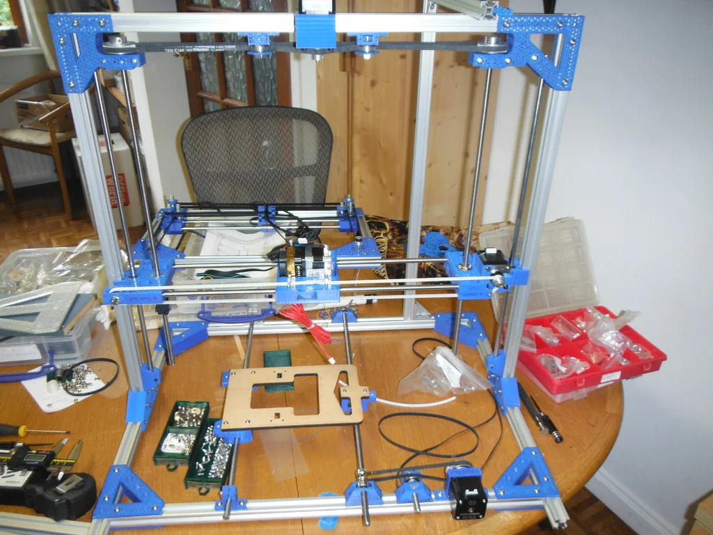
This is a RepRap 3D printer evolved from the orignal Mendel. It uses 2020 T-slot section for the frame rather than 8mm threaded rods. It has a single z-motor using a belt to drive 2 lead screws. The y-carriage uses a lead screw rather than a belt attached to the bed. I also took some time to get the x carriage belt to pull along the axis of one of the 8mm rods, with the possibility of quick change extruders/cutters/etchers in mind.
The size of the printer is determined by the length of the rods and lead screws you choose to use, which then drives then lengths of t-slot you need.
The original objective was to gain a better z-height as this was constraining some of my prints. I also wanted a more adaptable and physically open design to make changing extruders nozzles and cleaning the bed less of a fiddle. I have kept the x-carriage horizontal. I have increased the distance between the rods from the original Mendel to better fit the MK8 extruder. But if you want to fit an existing x-carriage you can chage it back (x_rod_centers parameter in CommonDimensions.scad). All the moving parts are inside the frame so I do not catch my jumper on the sticky out bits, it also has the potential for boxing the printer away from the dust and the fumes away from me.
I have had it wired up and working using a RAMPS board and Marlin firmware, but another project beckoned before I bit the bullet and replaced my trusty old mendels, so I have never been through he pain of comissioning it, or seen how wobbly it might get when working at height.
Printer:
Mendel - modified
Rafts:
No
Supports:
No
Resolution:
0.4 Nozzle 0.2 layer height
Infill:
25%
SCAD Stuff
Everything is now in a zip file.
All the stuff you need to print is inThings.scad, it also has a hardware list.
InHardware.scad puts most of the parts together to see how they are goiing to fit before you print them.
The actual parts are in: connecton_plates - L and T plates for 2020 t-slot end_stops - holders for end stop boards holders - stuff to hold things onto 2020 t-slot Geetech_Mount a carriage to put a MK8 extruder in x_carr the x-carriage parts y_mounts - the mounts for the y carriage z_motor - the stuff to hold the z motor z_mounts_corner - the corner plates that hold the z rods
Supprt files are: CommonDimensions - dimensions shared across the parts common_shapes - shapes used across the parts cutters - shapes to cut things out ofings washers - some washers you migh need LMU8 - definion of LMU8 bearings and blocks that fit them.
You also need these files in the same directory: thread_calc & printer_settings give you the ability to make things a set number of threads wide using the standard rectangle+2semicircle model for thread_width and build_width calculations. You should combine this with setting the thread_width in your Slicer (print settings/Advanced in Sic3r) rodsandholes - a set of functions to set the diameter and number of sides of a cylinder to be the correct internal or external diamiter for a rod or a hole metric_sizes - a set of numbers which do holes for metric bolts and nuts..
How to put the bits together
I have not yet found the optimal order for construction, last time my head saved the completed z assembly from falling on the floor when I failed to slot it into the t plates on the base. Suggest you don't put the z motor in until later, much lighter that way!
I know the explanation would be much better with pictures, please post some if you make one :)
Here are some notes, I hope they help.
Put a 608 inside each of the z corners and do them up with a couple of m4 nuts and bolts. Poke your z lead screw through the bearing, fiddle the thrust bearings into place and attach the bigger (60 tooth) pully (repeat for the other corner). Attach the top 2020 bar to the tops of the z corners and the 2 vertical bars to the sides.
Bolt the 608 into the slot in the x carriage pulley side with an M8 nut and bolt, slide the dry bearing into the z-rod hole and bolt the lead screw nut into place.
Fix the rod adjustment screws (M3 locknut and screw) into the slots your x rods will go into on x carrige motor side. Slide the dry bearing into the z-rod hole and bolt the lead screw nut into place. Put the motor in place and use a longer M3 screw to thread through the 623 bearing and into the motor, screw in the other 2 motor fixing screws. Fix a long M3 screw with a lock nut into the hole for the Z-adjustment thingy.
Place the LMU8 bearings in the extruder mounting trolly and secure the two halves together with 7 M3 screws and bolts (washers are good too) don't forget to put the belt clamps in place but do not tighten them up fully until you fit the belt.
Put the x rods in the pulley side, thread the extruder mount on and then the motor end. Thread you belt round the pulley and bearings and secure to the extruder trolly.
Thread the z lead screws on the Z assembly through the lead screw nuts on the x assembly. Push the z rods through the dry bearings and into the slots in the z-corner mounts. Secure the bottom of the z rods to the vertical 2020 bars with two y-rod holders. Mount the z end stop holder on the vertical bar below the x motor side.
Build the rectangle for the base plate with 4 2020 bars and 4 L plate sets. Add the T plates to oposite sides of your rectangle.
Slot the Z/X assembly into the vertical of the T plate.
If you have everything lined up nicely the x assembly will fall down the z screws and hit your end stop mount.
Fit the y rod to the base with 2 x rod holders.
Slide a couple of 608 bearings into the y_608_ends. Attach the one with the blank end at the non-motor side of your bed. Attach the lead screw nut to the y lead screw mount and thread it onto you y lead screw follow that with a small pully a thrust bearing and the other y_608_end. Put your y-belt around the screw. Poke the screw into the attached 608 end and drop the other one into the t-slot opposite. Fix the pulley in place tight against the thrust bearing.
Fix the y motor in the mount, fit the pulley and put it somewhere convenient to the size of your belt. Put an M8 nut in the y-tensioner, thread the tensioner plate another 608 and sufficient washers to line the 608 up with the lead screw pully (I found 3 was good). Fit the tensioner between the motor and the lead screw and shift it about to get a nice tension in the belt.
Fit the z-motor in its mount with a pulley and fix it in the middle of the top horizontal bar so the pulley hangs down. Slot an M8 nut into each z-tensioner, thread a tensioner plate and 608 bearing onto 2 short M8 bolts and screw them in. Mount the tensioners on the top 2020 bar each side of the motor. Thread you z-belt loosly round the 3 pullys, make sure you have enough slack to independently move the z screws during commissioning. Slide the tensioners towards the z-motor to get a nice tension in the belt.
Fit the heated bed assembly as per Mendel instructions and lastly the y end stop on the y-rod.
Now all you need to do is wire it up to a controller board and commission it getting everything true and square (you might want to print some spacer bars from connection_plates.scad to help).
Category: 3D Printers
Bytinx_1344834Likes1.2KDownloads6K

 ByreddLikes216Downloads2.1K

 ByJasonOlliff_519145Likes241Downloads2K

 Byarhi_585078Likes64Downloads536

 ByHanzo3dLikes155Downloads410

 ByGeek5DLikes147Downloads480

 ByBrokentooth_designsLikes23Downloads402

 By3DSourcererLikes48Downloads373

 ByWyomingWolf_261196Likes52Downloads423

 Byzachstofko_3956201Likes88Downloads151

 ByzooppLikes7Downloads158

 ByBlackky98Likes25Downloads204